100% Sicheres Einkaufen
Studio equipment
Our full range of studio equipment from all the leading equipment and software brands. Guaranteed fast delivery and low prices.
100% Sicheres Einkaufen
DJ equipment
Our full range of DJ equipment from all the leading equipment and software brands. Guaranteed fast delivery and low prices. Visit Juno DJ

Hilfe
BestellenProbleme beim BestellenHäufig gestellte FragenKontaktiere unsKontaktiere uns (Lieferanten)Über JunoJuno DailyNeuerscheinungen dieser WocheDJ & Studio StoreTagsFeedbackDatenschutzregelungReturns & refundsAGBFinanceJuno Vinyl DistributionJuno Vinyl WholesaleJuno Marketing and PR departmentPromote your label / releases


Filter

Equipment
Format
Release Date
2,949
Not Forthcoming
27
Last Week
41
Last 2 Weeks
68
Last Month
187
Last 2 Months
480
Last 6 Months
840
Last Year
Price
Tags
Back catalogue: Studio Equipment
Juno's full catalogue of Studio Equipment
Options
Sort
Artist
Artist
- Bestseller:
- Absteigend sortieren
- Artist:
- Alphabetisch sortieren (aufsteigend)
- Alphabetisch sortieren (absteigend)
- Title:
- Alphabetisch sortieren (aufsteigend)
- Alphabetisch sortieren (absteigend)
- Label:
- Alphabetisch sortieren (aufsteigend)
- Alphabetisch sortieren (absteigend)
- Date:
- Nach Alter sortieren (absteigend)
- Nach Alter sortieren (aufsteigend)
- Price:
- Nach Preis sortieren (aufsteigend)
- Nach Preis sortieren (absteigend)
- Label rank:
- Low to high
- High to low
People also bought...
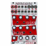
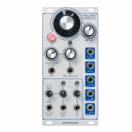
Cre8audio Function Junction Function Generator Module (attenuator/CV modulation/function generator/mixer/envelope generator/LFO module)
Cat: 872059 Rel: 26 Apr 22
Function generator module - 16HP
Notes: Function Junction
ADSR, Function Generator, LFO, & Mixer
According to the user manual, "Function Junction is a modulation hub combining four independent sections into a single intertwined module that offers much more than the sum of its parts. Although a sum of its parts is one of its best features!"- but Function Junction can do more than a ton of things. In fact, it's downright impressive what's possible with this lovely module.
Function Junction combines three classic analogue modulation sources, ADSR envelope, function generator, and LFO. All are fed into an attenuverting mixer to create a complex modulation junction that can be used as 4 independent sections or in conjunction with each other.
The magic of the module is the ease you can flow from using its functions for basic everyday tasks to creating hyper-complex modulation. The sheer breadth of what you can do and the ease of doing it are simply amazing. Cre8audio highly recommending reading the manual to get a feel for the possibilities.
Specifications
Width = 16hp
Depth = 30mm
Power draw: 130mA when running +12V rail, 70mA when running -12V
ADSR / Envelope facts
Fully analogue Pittsburgh Modular Synthesizers developed 4 stage ADSR circuit with independent Attack, Decay, Sustain and Release controls.
Voltage output range 0V - 10V
"Long" button doubles the length of the envelope attack, decay, and release times
"Loop" button enables/disables envelope cycling. The SUSTAIN KNOB and RELEASE KNOB are used to adjust the time it takes to loop.
"A LOOP JACK" - Enables/disable loop mode. An external gate signal will flip the state of the loop mode. If loop mode is on, the gate will turn loop mode off. If loop mode is off, the external gate will turn loop mode on.
Function Generator facts
Function Generator can be used as an envelope generator, a voltage controlled LFO, a slew generator, a gate signal delay, envelope follower, a clock source, voltage controlled clock divider, complex modulation source, and more
Voltage output range +/-5V
ATTACK KNOB - Attack duration control knob.
DECAY KNOB - Decay duration control knob.
CURVE KNOB - Attack and decay response curve. Exponential (full left), Linear (12 o'clock), Logarithmic (full right)
MOD KNOB - Modulation input (F MOD JACK) attenuverter knob.
MOD BUTTON - Assign Modulation input (F MOD JACK) to attack, decay, or both.
LOOP BUTTON - Enable/Disable loop mode.
LOOP BUTTON (2nd FUNCTION) - Press and hold MOD BUTTON then press LOOP BUTTON to assign A LOOP JACK destination to ADSR or function generator.
SUSTAIN BUTTON - Enable/Disable sustain mode.
F IN JACK - Function Generator trigger/gate input gate jack.
F MOD JACK - Function Generator modulation input jack.
F OUT JACK - Function Generator output jack.
F TRIG JACK - Function Generator end of decay trigger output jack. A trigger is output at the end of the decay stage.
LFO facts
Triangle and Square LFO outs
Dedicated rate knob
LFO output voltage +/-8V
Mixer facts
3 channel attenuverting mixer with OR circuit
Mixer can be split into 3 independent attenuverters, one two-channel mixer, and one attenuverter, or a three-channel mixer
OUTPUT 1 KNOB - Channel 1 input (1A JACK) attenuverter knob.
OUTPUT 2 KNOB - Channel 2 input (2F JACK) attenuverter knob.
OUTPUT 3 KNOB - Channel 3 input (3L JACK) attenuverter knob.
1A JACK - Channel 1 input jack. Normaled to ADSR output.
2F JACK - Channel 2 input jack. Normaled to function generator output.
3L JACK - Channel 3 input jack. Normaled to LFO output.
+OR JACK - Analog logic output jack.
OR circuit outputs the current highest voltage value of any of the voltages output by the mixer
1 OUT JACK - Channel 1 breakout output.
2 OUT JACK - Channel 2 breakout output.
MIX JACK - Mixer output.
… Read moreADSR, Function Generator, LFO, & Mixer
According to the user manual, "Function Junction is a modulation hub combining four independent sections into a single intertwined module that offers much more than the sum of its parts. Although a sum of its parts is one of its best features!"- but Function Junction can do more than a ton of things. In fact, it's downright impressive what's possible with this lovely module.
Function Junction combines three classic analogue modulation sources, ADSR envelope, function generator, and LFO. All are fed into an attenuverting mixer to create a complex modulation junction that can be used as 4 independent sections or in conjunction with each other.
The magic of the module is the ease you can flow from using its functions for basic everyday tasks to creating hyper-complex modulation. The sheer breadth of what you can do and the ease of doing it are simply amazing. Cre8audio highly recommending reading the manual to get a feel for the possibilities.
Specifications
Width = 16hp
Depth = 30mm
Power draw: 130mA when running +12V rail, 70mA when running -12V
ADSR / Envelope facts
Fully analogue Pittsburgh Modular Synthesizers developed 4 stage ADSR circuit with independent Attack, Decay, Sustain and Release controls.
Voltage output range 0V - 10V
"Long" button doubles the length of the envelope attack, decay, and release times
"Loop" button enables/disables envelope cycling. The SUSTAIN KNOB and RELEASE KNOB are used to adjust the time it takes to loop.
"A LOOP JACK" - Enables/disable loop mode. An external gate signal will flip the state of the loop mode. If loop mode is on, the gate will turn loop mode off. If loop mode is off, the external gate will turn loop mode on.
Function Generator facts
Function Generator can be used as an envelope generator, a voltage controlled LFO, a slew generator, a gate signal delay, envelope follower, a clock source, voltage controlled clock divider, complex modulation source, and more
Voltage output range +/-5V
ATTACK KNOB - Attack duration control knob.
DECAY KNOB - Decay duration control knob.
CURVE KNOB - Attack and decay response curve. Exponential (full left), Linear (12 o'clock), Logarithmic (full right)
MOD KNOB - Modulation input (F MOD JACK) attenuverter knob.
MOD BUTTON - Assign Modulation input (F MOD JACK) to attack, decay, or both.
LOOP BUTTON - Enable/Disable loop mode.
LOOP BUTTON (2nd FUNCTION) - Press and hold MOD BUTTON then press LOOP BUTTON to assign A LOOP JACK destination to ADSR or function generator.
SUSTAIN BUTTON - Enable/Disable sustain mode.
F IN JACK - Function Generator trigger/gate input gate jack.
F MOD JACK - Function Generator modulation input jack.
F OUT JACK - Function Generator output jack.
F TRIG JACK - Function Generator end of decay trigger output jack. A trigger is output at the end of the decay stage.
LFO facts
Triangle and Square LFO outs
Dedicated rate knob
LFO output voltage +/-8V
Mixer facts
3 channel attenuverting mixer with OR circuit
Mixer can be split into 3 independent attenuverters, one two-channel mixer, and one attenuverter, or a three-channel mixer
OUTPUT 1 KNOB - Channel 1 input (1A JACK) attenuverter knob.
OUTPUT 2 KNOB - Channel 2 input (2F JACK) attenuverter knob.
OUTPUT 3 KNOB - Channel 3 input (3L JACK) attenuverter knob.
1A JACK - Channel 1 input jack. Normaled to ADSR output.
2F JACK - Channel 2 input jack. Normaled to function generator output.
3L JACK - Channel 3 input jack. Normaled to LFO output.
+OR JACK - Analog logic output jack.
OR circuit outputs the current highest voltage value of any of the voltages output by the mixer
1 OUT JACK - Channel 1 breakout output.
2 OUT JACK - Channel 2 breakout output.
MIX JACK - Mixer output.
1 in stock $176.23
People also bought...
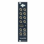
Crosspatch Triggerpad Dynamic Trigger Sequencer Module (sequencer module)
Cat: 995020 Rel: 04 Apr 24
8-channel sequencer module - 6HP
Notes: Neat little interface module to help pad controllers play nicely with Eurorack. Hook up a device like a Launchpad or APC and jam out rhythms with retriggering options, dynamic control and MIDI sync.
Supplier's Notes:
Triggerpad is a dynamic trigger/gate sequencer in eurorack format on only 6hp. A USB MIDI controller with an 8×8 grid like Launchpad or APC is used to display and edit the patterns (see the list of compatible controllers). The user experience is tailored to live performance and detailed composition: dial in simple rhythms or complex polyrhythms, retrigger at audio rate, create dynamic percussions with velocity triggers or use longer pulses to create steppy modulations.
By using USB MIDI controllers that you might already have and maybe not use anymore, we avoid producing more plastic. Give your old gear a second life!
Dimensions & consumption
Width: 6hp
Depth: 39mm
+12V: 120mA (without USB MIDI controller connected)
-12V: 20mA
5V: 0mA
USB MIDI controllers consume up to 150mA on +12V
Connectivity
8 dynamic trigger/gate outputs (0-10V)
USB MIDI Host
Clock in
Clock out
Reset in
Reset out
Compatibility
Launchpad Pro Mk3
Launchpad X
Launchpad Mini Mk3
Launchpad Mini Mk2
Launchpad Pro
Launchpad Mk2
Launchpad S
APC Mini Mk1
APC Mini Mk2
… Read moreSupplier's Notes:
Triggerpad is a dynamic trigger/gate sequencer in eurorack format on only 6hp. A USB MIDI controller with an 8×8 grid like Launchpad or APC is used to display and edit the patterns (see the list of compatible controllers). The user experience is tailored to live performance and detailed composition: dial in simple rhythms or complex polyrhythms, retrigger at audio rate, create dynamic percussions with velocity triggers or use longer pulses to create steppy modulations.
By using USB MIDI controllers that you might already have and maybe not use anymore, we avoid producing more plastic. Give your old gear a second life!
Dimensions & consumption
Width: 6hp
Depth: 39mm
+12V: 120mA (without USB MIDI controller connected)
-12V: 20mA
5V: 0mA
USB MIDI controllers consume up to 150mA on +12V
Connectivity
8 dynamic trigger/gate outputs (0-10V)
USB MIDI Host
Clock in
Clock out
Reset in
Reset out
Compatibility
Launchpad Pro Mk3
Launchpad X
Launchpad Mini Mk3
Launchpad Mini Mk2
Launchpad Pro
Launchpad Mk2
Launchpad S
APC Mini Mk1
APC Mini Mk2
2 in stock $312.84
Click for better price!
or call +44 20 7424 1960
quote 995020
quote 995020
People also bought...
Dannysound Cali Oscillator Wave Shaping Oscillator Module (LFO/oscillator synth module)
Cat: 967569 Rel: 15 Sep 23
Wave shaping oscillator module with touch sensitive switch - 12HP.
Notes: The Cali oscillator is a new and improved version of the classic Buchla 258 wave shaping oscillator with an additional pulse width modulated output. The oscillator features the classic Sine to Square and Sine to Saw wave shaping with dedicated CV control. The Cali Oscillator differs from previous versions of the 258 in that it has a 3-way position switch rather than 2-way. This new middle position features a bonus waveform that will shape from a pulse into a kind of triangular trapezoid shape. The shaping control is more unpredictable in this middle position and the switch reacts to body contact when the wave shape is set low - it can be thought of as an extra bonus waveform, great for producing glitchy sounds! There are dedicated inputs for linear and exponential FM and the Cali also adds a Pulse output with it's own width control and PWM CV input. The behaviour of the pulse output can be affected by the position of the waveform switch and wave shape control. The module features Coarse and Fine frequency controls and an LFO mode, LFO range is accessed via an LED pushbutton that also acts as the LFO speed indicator - the button will light up when the waveform moves through its positive cycle. Because the wave shape modulation is independent of pitch this oscillator is very useful for creating complex timbres whilst retaining musical pitch.
Features
Sine to saw/square waveform output with cv over wave shaping
Pulse output with voltage controlled PWM
Linear FM with attenuator
Logarithmic FM with attenuator
Bonus 'trapezoid' output
Coarse & fine controls with LFO mode
Includes power supply isolation on frequency controls
Width: 12 HP
Depth: 22mm
Power
+12V = 37mA
-12V = 34mA
… Read moreFeatures
Sine to saw/square waveform output with cv over wave shaping
Pulse output with voltage controlled PWM
Linear FM with attenuator
Logarithmic FM with attenuator
Bonus 'trapezoid' output
Coarse & fine controls with LFO mode
Includes power supply isolation on frequency controls
Width: 12 HP
Depth: 22mm
Power
+12V = 37mA
-12V = 34mA
1 in stock $238.59
Click for better price!
or call +44 20 7424 1960
quote 967569
quote 967569
People also bought...
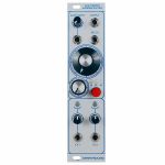
Dannysound Dynamics Analogue Compressor/Expander Module (dynamics synth module)
Cat: 967575 Rel: 15 Sep 23
Analogue compressor/expander module with inductor EQ section, sub bass enhancer and harmonic exciter - 12HP.
Notes: The Dannysound Dynamics is a compressor / expander originally designed to process drums but, like most processing devices, it can be used for a wide variety of applications.
The module comprises of:
Compressor / Expander
Sub Bass Enhancer
3 Band Inductor-based EQ
Harmonic Exciter
The compressor / expander section uses a discrete transistor-based circuit that allows for soft clipping when overdriven.
The envelope detector is known as a feedforward type of circuit; taking its input from the signal before it goes to the compressor rather than after. This type of circuit is known for having fast attack times.
The Sub Bass enhancer has its own compression circuit that "ducks" the initial transient. This allows the sub bass to be increased without distortion on the transient peaks, increasing the overall level.
There is a MIX control to allow the unprocessed signal to be mixed back in with the processed signal.
The 3 band EQ is an inductor based LCR design. After Dannysound tryed out various EQ topologies, this was the design that sounded the nicest. When overdriven it gives a nice "bite" to the sound, and it has a certain characterful charm that's hard to put into words. The controls have a response that are subtle to begin with and get more pronounced as the controls are increased.
The Harmonic Exciter adds a little distortion to the high frequencies, which bring out the sparkle of cymbals or the snap snare drums. The operating bandwidth can be switched between Low (snare drum snap) or High (Cymbals sparkle).
There are inputs for side chaining and control with an external envelope as well as an envelope out to make the envelope detector output available to drive other modules.
It also features separate inputs and outputs for the Compressor / Expander and EQ sections, so they could be used as 2 separate modules.
Features:
Compressor/ Expander
Sub Bass Enhancer
3 Band Inductor-Based EQ
Harmonic Exciter
Envelope In/Out
Sidechain Input
Seperate In/Out for Compressor, Expander and EQ-Section
Power consumption: 85mA at +12V and 61mA at -12V
Depth: 25mm
HP : 12
… Read moreThe module comprises of:
Compressor / Expander
Sub Bass Enhancer
3 Band Inductor-based EQ
Harmonic Exciter
The compressor / expander section uses a discrete transistor-based circuit that allows for soft clipping when overdriven.
The envelope detector is known as a feedforward type of circuit; taking its input from the signal before it goes to the compressor rather than after. This type of circuit is known for having fast attack times.
The Sub Bass enhancer has its own compression circuit that "ducks" the initial transient. This allows the sub bass to be increased without distortion on the transient peaks, increasing the overall level.
There is a MIX control to allow the unprocessed signal to be mixed back in with the processed signal.
The 3 band EQ is an inductor based LCR design. After Dannysound tryed out various EQ topologies, this was the design that sounded the nicest. When overdriven it gives a nice "bite" to the sound, and it has a certain characterful charm that's hard to put into words. The controls have a response that are subtle to begin with and get more pronounced as the controls are increased.
The Harmonic Exciter adds a little distortion to the high frequencies, which bring out the sparkle of cymbals or the snap snare drums. The operating bandwidth can be switched between Low (snare drum snap) or High (Cymbals sparkle).
There are inputs for side chaining and control with an external envelope as well as an envelope out to make the envelope detector output available to drive other modules.
It also features separate inputs and outputs for the Compressor / Expander and EQ sections, so they could be used as 2 separate modules.
Features:
Compressor/ Expander
Sub Bass Enhancer
3 Band Inductor-Based EQ
Harmonic Exciter
Envelope In/Out
Sidechain Input
Seperate In/Out for Compressor, Expander and EQ-Section
Power consumption: 85mA at +12V and 61mA at -12V
Depth: 25mm
HP : 12
1 in stock $360.82
Click for better price!
or call +44 20 7424 1960
quote 967575
quote 967575
People also bought...
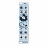
Dannysound EN129 Thru-Zero Oscillator Module (LFO/oscillator synth module)
Cat: 967572 Rel: 15 Sep 23
Through zero oscillator module - 12HP.
Notes: Gorgeous vintage-style through-zero FM here, featuring five simultaneous waveform outputs, pulse width modulation, soft sync and a dedicated LFO mode.
Supplier's notes:
The EN129 Thru Zero Oscillator is an all analogue triangle-core VCO specialising in frequency modulation. Analogue through-zero FM modulation produces a wide array of timbres particularly useful for bell like or percussive sounds. Through zero linear frequency modulation can be precisely dialled in thanks to a dedicated CV input attenuator and through zero offset control. Logarithmic FM is also available via it's own dedicated input with attenuator and both FM inputs have an LED to indicate incoming voltages. Simultaneous analogue wave outputs include: Sine, Triangle, Sawtooth, Square and Pulse wave with Pulse Width Modulation. The PWM control goes to zero at either end of it's range, which is very useful for creating rhythmic sounds with voltage control. Furthermore the PWM control doubles up as wave shape modulation for the Sawtooth wave - gradually altering the waveform until it shifts half a cycle. The EN129 features Coarse and Fine frequency controls as well as an LFO mode. LFO range is accessed via an LED pushbutton that also acts as the LFO speed indicator - the button will light up when the waveform moves through its positive cycle. A new addition of a Soft Sync Input allows the phase of the oscillator to be controlled by an external oscillator for an even greater range of timbres.
The EN129 is based on the pioneering work by Douglas Kraul and Bernie Hutchins. You can read the original Electronotes article from 1981 that the design is based upon here.
Features:
Soft Sync Input
Thru Zero Linear FM
Logarithmic FM
Zero to Zero PWM
Sawtooth Wave Shape Modulation
Simultaneous Outputs for: Sine, Triangle, Saw, Pulse & Square
Coarse & Fine Controls with LFO Mode
Includes Power Supply Isolation on Frequency Controls
Power consumption: 51mA at +12V and 47mA at -12V
Depth: 22mm
HP : 12
… Read moreSupplier's notes:
The EN129 Thru Zero Oscillator is an all analogue triangle-core VCO specialising in frequency modulation. Analogue through-zero FM modulation produces a wide array of timbres particularly useful for bell like or percussive sounds. Through zero linear frequency modulation can be precisely dialled in thanks to a dedicated CV input attenuator and through zero offset control. Logarithmic FM is also available via it's own dedicated input with attenuator and both FM inputs have an LED to indicate incoming voltages. Simultaneous analogue wave outputs include: Sine, Triangle, Sawtooth, Square and Pulse wave with Pulse Width Modulation. The PWM control goes to zero at either end of it's range, which is very useful for creating rhythmic sounds with voltage control. Furthermore the PWM control doubles up as wave shape modulation for the Sawtooth wave - gradually altering the waveform until it shifts half a cycle. The EN129 features Coarse and Fine frequency controls as well as an LFO mode. LFO range is accessed via an LED pushbutton that also acts as the LFO speed indicator - the button will light up when the waveform moves through its positive cycle. A new addition of a Soft Sync Input allows the phase of the oscillator to be controlled by an external oscillator for an even greater range of timbres.
The EN129 is based on the pioneering work by Douglas Kraul and Bernie Hutchins. You can read the original Electronotes article from 1981 that the design is based upon here.
Features:
Soft Sync Input
Thru Zero Linear FM
Logarithmic FM
Zero to Zero PWM
Sawtooth Wave Shape Modulation
Simultaneous Outputs for: Sine, Triangle, Saw, Pulse & Square
Coarse & Fine Controls with LFO Mode
Includes Power Supply Isolation on Frequency Controls
Power consumption: 51mA at +12V and 47mA at -12V
Depth: 22mm
HP : 12
1 in stock $224.85
People also bought...
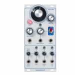
Dannysound Looping VC-ADSR 4-Stage Envelope Generator Module (envelope generator/function generator/LFO synth module)
Cat: 967622 Rel: 15 Sep 23
ADSR envelope module with full CV control and looping LFO mode - 6HP.
Notes: The Looping VC-ADSR is a 4-stage, loop-able, envelope generator based on the ENVGEN 8C IC from Electric Druid. The individual sections of the Envelope (Attack, Decay, Sustain, Release, Level and Time) can all be individually controlled via CV.
The module has 5 MODES of operation that can be selected via the pushbutton LED switch with the status indicated by the five LEDs above:
Normal Envelope - Gate signal at the GATE/TRIG input, fires the ADSR.
Trigger Mode - Trigger signal at the GATE/TRIG input fires the AD portion of the envelope. The sustain control determines the final value the envelope rests at after the decay portion has ended.
Gated Looping Envelope - ADSR loops whilst gate signal is high.
Looping Envelope - ADSR loops regardless of gate signal.
LIN response (Hold switch to select between LIN/EXP Mode) - Sets the envelope response to be Linear. The response is Exponential when the status LED is off.
When the envelope is looping, all 5 controls affect the output. Attack and Decay operate, as one would expect. The Sustain control sets the minimum voltage the decay part of the envelope will decay to. The Release sets a release time from the end of the Sustain period to the beginning of the next cycle. When the Sustain is set to 0 you can use the Release control to add a delay between the Attack and Decay cycles.
In Normal Envelope mode the Sustain CV input can be used with an LFO source to add amplitude modulation that gradually increases as the Envelope transitions from the Attack/Decay part of the envelope into the Sustain part. The Level CV is also a useful point for amplitude modulation or can be used for Velocity Sensitivity via CV.
The Time CV is set so that increasing voltage shortens the overall envelope time to better mimic the sounds of percussive instruments.
Features:
5 Modes of Operation: Gate Input ADSR, Trigger Input ADS, Gated Loop, Constant Loop and EXP/LIN Envelope Responses
CV over: Attack, Decay, Sustain, Release, Level and Time
Works with Gate or Trigger Signals from +5V to +12V
CV Input Range 0V to +10V
Output CV Range 0V to +10V
Power consumption: 28mA at +12V and 18mA at -12V
Depth: 25mm
HP : 6
… Read moreThe module has 5 MODES of operation that can be selected via the pushbutton LED switch with the status indicated by the five LEDs above:
Normal Envelope - Gate signal at the GATE/TRIG input, fires the ADSR.
Trigger Mode - Trigger signal at the GATE/TRIG input fires the AD portion of the envelope. The sustain control determines the final value the envelope rests at after the decay portion has ended.
Gated Looping Envelope - ADSR loops whilst gate signal is high.
Looping Envelope - ADSR loops regardless of gate signal.
LIN response (Hold switch to select between LIN/EXP Mode) - Sets the envelope response to be Linear. The response is Exponential when the status LED is off.
When the envelope is looping, all 5 controls affect the output. Attack and Decay operate, as one would expect. The Sustain control sets the minimum voltage the decay part of the envelope will decay to. The Release sets a release time from the end of the Sustain period to the beginning of the next cycle. When the Sustain is set to 0 you can use the Release control to add a delay between the Attack and Decay cycles.
In Normal Envelope mode the Sustain CV input can be used with an LFO source to add amplitude modulation that gradually increases as the Envelope transitions from the Attack/Decay part of the envelope into the Sustain part. The Level CV is also a useful point for amplitude modulation or can be used for Velocity Sensitivity via CV.
The Time CV is set so that increasing voltage shortens the overall envelope time to better mimic the sounds of percussive instruments.
Features:
5 Modes of Operation: Gate Input ADSR, Trigger Input ADS, Gated Loop, Constant Loop and EXP/LIN Envelope Responses
CV over: Attack, Decay, Sustain, Release, Level and Time
Works with Gate or Trigger Signals from +5V to +12V
CV Input Range 0V to +10V
Output CV Range 0V to +10V
Power consumption: 28mA at +12V and 18mA at -12V
Depth: 25mm
HP : 6
2 in stock $270.09
Click for better price!
or call +44 20 7424 1960
quote 967622
quote 967622
People also bought...
Dannysound MML Filter Multi-Mode Ladder Filter Module (distortion/filter synth module)
Cat: 967619 Rel: 12 Dec 23
Multimode transistor ladder filter module with red mode feedback distortion - 6HP.
Notes: The updated "Skiff friendly" design of the mml filter now features bipolar "Attenu-verters" for the cv controls as well as an all new red mode!
This new mode activates a feedback distortion circuit capable of actually changing the pitch of the notes coming in to the filter in a musical way that adds instant variety to acid basslines, creates weird and strange alterations to drones or adds some nice overdriven distortion to whatever goes into it!
The multi-mode ladder (mml) filter is based on the classic transistor ladder low pass filter by dr. Robert a. Moog. This filter updates the classic 4-pole ladder design to provide band pass and high pass filter responses as well as the traditional low pass filter. There are 2 bipolar controls with attenu-verters for the cut-off frequency plus a cv input for the resonance.
The core of the circuit features a fully discrete transistor design with an op-amp buffered output, this allows soft saturation of the input signal to get the classic overdriven tones of the ladder filter. A bass compensation circuit has been included to retain the bass response in low pass mode when the resonance is increased. The bass compensation also helps to improve the response of the high pass filter.
The red mode is activated/de-activated by holding the mode button for 0.3s. In this mode the filter cut-off, input volume and resonance all interact and the effect is to produce alterations to the incoming frequencies. The pitches of the audio coming into the filter also affect the alterations as well selecting between low pass, band pass and high pass filter modes whilst in red mode.
Features
Low pass, band pass and high pass modes.
Red mode feedback distortion.
CV controlled resonance.
Added low frequency compensation.
Soft saturation of input.
2 x bipolar attenuverter CV inputs.
Width: 6 HP
Depth: 25mm
Power: +12v = 50ma / -12v = 39ma
… Read moreThis new mode activates a feedback distortion circuit capable of actually changing the pitch of the notes coming in to the filter in a musical way that adds instant variety to acid basslines, creates weird and strange alterations to drones or adds some nice overdriven distortion to whatever goes into it!
The multi-mode ladder (mml) filter is based on the classic transistor ladder low pass filter by dr. Robert a. Moog. This filter updates the classic 4-pole ladder design to provide band pass and high pass filter responses as well as the traditional low pass filter. There are 2 bipolar controls with attenu-verters for the cut-off frequency plus a cv input for the resonance.
The core of the circuit features a fully discrete transistor design with an op-amp buffered output, this allows soft saturation of the input signal to get the classic overdriven tones of the ladder filter. A bass compensation circuit has been included to retain the bass response in low pass mode when the resonance is increased. The bass compensation also helps to improve the response of the high pass filter.
The red mode is activated/de-activated by holding the mode button for 0.3s. In this mode the filter cut-off, input volume and resonance all interact and the effect is to produce alterations to the incoming frequencies. The pitches of the audio coming into the filter also affect the alterations as well selecting between low pass, band pass and high pass filter modes whilst in red mode.
Features
Low pass, band pass and high pass modes.
Red mode feedback distortion.
CV controlled resonance.
Added low frequency compensation.
Soft saturation of input.
2 x bipolar attenuverter CV inputs.
Width: 6 HP
Depth: 25mm
Power: +12v = 50ma / -12v = 39ma
1 in stock $269.04
Click for better price!
or call +44 20 7424 1960
quote 967619
quote 967619
People also bought...
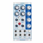
Dannysound Timbre Buchla 259 Inspired Wavefolder Module (mixer/waveshaper synth module)
Cat: 967621 Rel: 15 Sep 23
Buchla 259 inspired wavefolder module - 6HP.
Notes: The Timbre is a 6HP Eurorack module based on the wave folder section of the Buchla 259 oscillator as implemented in the Music Easel.
The wave folder adds extra harmonics to input signals that have low harmonic content to create rich and interesting timbres. Typical input sources to use would be Sine and Triangle waves but you are welcome to try other sources as well! The Dannysound Timbre adds an extra input to the Buchla design to allow 2 oscillators to drive the wave-folder simultaneously - this dramatically increases the range of possible tones that can be generated and allows the folder to go wild!
Features:
Osc1 / Osc2 Mix - Adjusts the mix between the Oscillator 1 and 2 inputs, also acts as an attenuator if only one input is used.
Timbre Control - Adjusts the overall amount of wave fold
Timbre CV - Bipolar (attenuator) controls the Timbre CV input
Symmetry - Adds an offset to the input so that the top half of the wave begins to fold earlier
Blend - Mixes between the clean and effected sound
Power consumption: 46mA at +12V and 48mA at -12V
Depth: 25mm
HP : 6
… Read moreThe wave folder adds extra harmonics to input signals that have low harmonic content to create rich and interesting timbres. Typical input sources to use would be Sine and Triangle waves but you are welcome to try other sources as well! The Dannysound Timbre adds an extra input to the Buchla design to allow 2 oscillators to drive the wave-folder simultaneously - this dramatically increases the range of possible tones that can be generated and allows the folder to go wild!
Features:
Osc1 / Osc2 Mix - Adjusts the mix between the Oscillator 1 and 2 inputs, also acts as an attenuator if only one input is used.
Timbre Control - Adjusts the overall amount of wave fold
Timbre CV - Bipolar (attenuator) controls the Timbre CV input
Symmetry - Adds an offset to the input so that the top half of the wave begins to fold earlier
Blend - Mixes between the clean and effected sound
Power consumption: 46mA at +12V and 48mA at -12V
Depth: 25mm
HP : 6
1 in stock $250.27
Click for better price!
or call +44 20 7424 1960
quote 967621
quote 967621
People also bought...
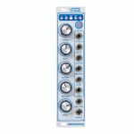
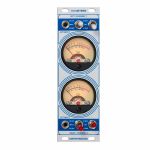
Dannysound VU Meters Analogue VU Meters Expander Module For Dynamics (dynamics/expander synth module)
Cat: 967625 Rel: 15 Sep 23
Analogue VU meters expander module for the Dynamics module - 8HP.
Notes: The Dannysound VU Meters is designed to be used with 2 x Dynamics modules. The modules connect internally via 2x3 pin ribbon cables. The meters provide a visual representation of various signals within the Dynamics modules making settings easier.
Features:
External input sockets for monitoring external sources.
Switch to select high or low meter sensitivity or off if the clicking needles get annoying!
Monitoring of the compression/expansion amount.
Monitoring of the unprocessed input level.
Monitoring of the compressor/expander output level.
Power consumption: 0.03mA at +12V and 83mA at -12V at and 3mA at +5V
Depth: 51mm
HP : 8
… Read moreFeatures:
External input sockets for monitoring external sources.
Switch to select high or low meter sensitivity or off if the clicking needles get annoying!
Monitoring of the compression/expansion amount.
Monitoring of the unprocessed input level.
Monitoring of the compressor/expander output level.
Power consumption: 0.03mA at +12V and 83mA at -12V at and 3mA at +5V
Depth: 51mm
HP : 8
1 in stock $220.03
Click for better price!
or call +44 20 7424 1960
quote 967625
quote 967625
People also bought...
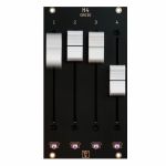
Der Mann Mit Der Maschine Droid M4 Motor Fader Controller Module (controller module)
Cat: 913511 Rel: 07 Dec 22
DROID M4 motor fader controller with 4 faders
Notes: This module provides you with four motorised faders (aka flying faders) to be attached to your DROID master. You can attach up to 16 of these units (or any other DROID controllers) to one master, so the maximum number of faders on a DROID is 64. Below each fader is a touch button and an LED.
You can use the faders, the buttons and the LEDs in very flexible ways to control all parameters in your DROID patches, like steps of a sequence, volumes of channels of a digital mixer (controlled via MIDI with the X7), parameters of a large bank of envelopes, CV values that are organized in presets and much more.
The special thing about the motorized faders is that each fader can be assigned several functions or presets. When you switch the function, the fader moves to the exact position that corresponds to the current value. The usual Eurorack "picking up" of potentiometers or faders, where you never know exactly which value is currently set, is now a thing of the past.
Another unique feature is the "haptic feedback". If a fader is used, for example, in a sequencer to select a note from a scale, you can feel each individual note like an artificial notch. The fader intelligently creates these virtual grooves with its motor. This is very useful and very intuitive whenever you use the fader to select one out of several discrete values. Other examples are clock divider settings, the number of a preset, a waveform, a clock offset and much more. Due to the haptic feedback you don't need any display for seeing what you are doing. You can concentrate on making music and play very intuitively.
Another kind of haptic feedback is a kind of "pitch bend wheel", where the fader always pushes back to the center position by itself. Here the motor creates an artifcial spring. When setting analog values such as a volume or a filter cutoff, the fader then runs freely, of course.
Applications
The DROID plus the faders can be used for various applications - and due to the possibility of switching even at the same time! Here are some example:
A multi track performance sequencer
Use a MIDI controllable digital audio interface as mixer
Control a bank of four envelopes with A, D, S, R each with just four faders
Use the faders for CV presets
Use the faders and their haptic feedback for live performing with pitch bends, ratcheting and all other crazy stuff
Power
Motor faders need much energy. Theoretically one single fader can draw up to 800 mA when at full power. That seems to be the main reason why nobody dared in bringing motorised faders into Eurorack so far.
Der Mann Mit Der Maschine have solved that challenge by making use of the fact that the fader need their power always just for a very short time. The M4 unit comes with four big power tanks (called super caps) that are loaded with a low current but provide the full power when the faders need them. That way the maximum current of one M4 unit is limited. With jumpers on the back you can choose between a peak current of 350, 450, 500 or 600 mA.
Dimensions
14 HP
42 mm deep
Current Draw
350 mA +12V
… Read moreYou can use the faders, the buttons and the LEDs in very flexible ways to control all parameters in your DROID patches, like steps of a sequence, volumes of channels of a digital mixer (controlled via MIDI with the X7), parameters of a large bank of envelopes, CV values that are organized in presets and much more.
The special thing about the motorized faders is that each fader can be assigned several functions or presets. When you switch the function, the fader moves to the exact position that corresponds to the current value. The usual Eurorack "picking up" of potentiometers or faders, where you never know exactly which value is currently set, is now a thing of the past.
Another unique feature is the "haptic feedback". If a fader is used, for example, in a sequencer to select a note from a scale, you can feel each individual note like an artificial notch. The fader intelligently creates these virtual grooves with its motor. This is very useful and very intuitive whenever you use the fader to select one out of several discrete values. Other examples are clock divider settings, the number of a preset, a waveform, a clock offset and much more. Due to the haptic feedback you don't need any display for seeing what you are doing. You can concentrate on making music and play very intuitively.
Another kind of haptic feedback is a kind of "pitch bend wheel", where the fader always pushes back to the center position by itself. Here the motor creates an artifcial spring. When setting analog values such as a volume or a filter cutoff, the fader then runs freely, of course.
Applications
The DROID plus the faders can be used for various applications - and due to the possibility of switching even at the same time! Here are some example:
A multi track performance sequencer
Use a MIDI controllable digital audio interface as mixer
Control a bank of four envelopes with A, D, S, R each with just four faders
Use the faders for CV presets
Use the faders and their haptic feedback for live performing with pitch bends, ratcheting and all other crazy stuff
Power
Motor faders need much energy. Theoretically one single fader can draw up to 800 mA when at full power. That seems to be the main reason why nobody dared in bringing motorised faders into Eurorack so far.
Der Mann Mit Der Maschine have solved that challenge by making use of the fact that the fader need their power always just for a very short time. The M4 unit comes with four big power tanks (called super caps) that are loaded with a low current but provide the full power when the faders need them. That way the maximum current of one M4 unit is limited. With jumpers on the back you can choose between a peak current of 350, 450, 500 or 600 mA.
Dimensions
14 HP
42 mm deep
Current Draw
350 mA +12V
1 in stock $442.16
Click for better price!
or call +44 20 7424 1960
quote 913511
quote 913511
People also bought...
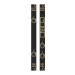
Der Mann Mit Der Maschine R2M/R2C Controller Remote Connection Modules For Droid Master (pair) (controller/uility module)
Cat: 971155 Rel: 06 Nov 23
R2M/R2C: two controller remote connection modules for the Droid Master - 2HP each.
Notes: R2M is module 1 of a pair of two 2 HP modules that allow you to connect a chain of controllers to your DROID master through a standard 3.5 mm stereo cable (sometimes also called aux-cable).
The usual idea is that you put all your DROID controllers into a skiff case and mount your DROID master, X7 and G8 into another case, together with all your fancy Eurorack sound modules.
R2C is module 2 of a pair of two 2 HP modules that allow you to connect a chain of controllers to your DROID master through a standard 3.5 mm stereo cable (sometimes also called aux-cable).
The usual idea is that you put all your DROID controllers into a skiff case and mount your DROID master, X7 and G8 into another case, together with all your fancy Eurorack sound modules.
While you could do this with the typical 6-pin ribbon connector (e.g. the 80 cm version that we offer), using the R2M/R2C combination has some serious advantages:
The connection cable can be almost arbitrary long (20 m have been tested and works perfectly).
Since the connection is done on the front of the modules, you can quickly disconnect your skiff for the purpose of travelling to a gig.
You can use a standard 3.5 mm stereo TRS cable for the connection.
These modules are not just passive connectors but contain special driver ICs that transform the electronic voltage levels, which run in the 6-pin ribbon, to something more stable and reliable that is fit for longer distances in a more hostile environment.
The controllers do not receive their power from the master but from the R2C module, which has a power connector and a voltage regulator for that purpose. Each chain of the R2C module provides the same power to its controller chain as the master does (it contains the identical voltage regulator). That means that you can connect up to 32 controllers (!) to one R2C.
Another nice thing: The R2M/R2C combination allows for two of these master / controller connections in parallel. That means that you can have two masters being attached to their individual controller chains. That does not mean, that each of the masters can access each of the controllers at the same time, however. Both master / controller connections work completely separately.
Package contents:
* one R2M module
* one R2C module
* one Eurorack power cable for the R2C
* two 6-pin ribbon cables for connecting the R2M to two masters
* two 3.5 mm stereo TRS cables, approx.. 1.2 m
* 4 red M3 screws for mounting the two modules
… Read moreThe usual idea is that you put all your DROID controllers into a skiff case and mount your DROID master, X7 and G8 into another case, together with all your fancy Eurorack sound modules.
R2C is module 2 of a pair of two 2 HP modules that allow you to connect a chain of controllers to your DROID master through a standard 3.5 mm stereo cable (sometimes also called aux-cable).
The usual idea is that you put all your DROID controllers into a skiff case and mount your DROID master, X7 and G8 into another case, together with all your fancy Eurorack sound modules.
While you could do this with the typical 6-pin ribbon connector (e.g. the 80 cm version that we offer), using the R2M/R2C combination has some serious advantages:
The connection cable can be almost arbitrary long (20 m have been tested and works perfectly).
Since the connection is done on the front of the modules, you can quickly disconnect your skiff for the purpose of travelling to a gig.
You can use a standard 3.5 mm stereo TRS cable for the connection.
These modules are not just passive connectors but contain special driver ICs that transform the electronic voltage levels, which run in the 6-pin ribbon, to something more stable and reliable that is fit for longer distances in a more hostile environment.
The controllers do not receive their power from the master but from the R2C module, which has a power connector and a voltage regulator for that purpose. Each chain of the R2C module provides the same power to its controller chain as the master does (it contains the identical voltage regulator). That means that you can connect up to 32 controllers (!) to one R2C.
Another nice thing: The R2M/R2C combination allows for two of these master / controller connections in parallel. That means that you can have two masters being attached to their individual controller chains. That does not mean, that each of the masters can access each of the controllers at the same time, however. Both master / controller connections work completely separately.
Package contents:
* one R2M module
* one R2C module
* one Eurorack power cable for the R2C
* two 6-pin ribbon cables for connecting the R2M to two masters
* two 3.5 mm stereo TRS cables, approx.. 1.2 m
* 4 red M3 screws for mounting the two modules
1 in stock $141.31
Click for better price!
or call +44 20 7424 1960
quote 971155
quote 971155
People also bought...
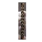
Der Mann Mit Der Maschine TRS Split CV/Audio Signal Distributor Module (dual/stereo/MIDI/utility module)
Cat: 1005286 Rel: 07 Mar 24
CV & audio signal distributor module - 2HP
Notes: TRS Split - CV/Audio signal distributor
TRS Split is a multipurpose CV and audio signal distribution module. It has three 3.5 mm TRS (tip/ring/sleeve - stereo) jacks and six ordinary 3.5 mm mono jacks.
It contains 3 identical sections set up as following:
Upper jack carries the tip signal
Middle jack carries the stereo/dual signal
Lower jack carries the ring signal
Each section can either split a stereo signal into two mono signals or join two mono signals into one stereo signal. The module does not have any active components and does not need a power supply.
Use cases:
When you plug a stereo signal carried by a stereo (TRS) cable into the middle jack, you receive two separate mono signals by plugging in a mono (TS) cable in the upper jack to carry the left signal and a mono (TS) cable in the lower jack to carry the right signal. That way you can attack an "AUX" cable such as from your smartphone to your modular.
Or the other way around: Send two separate mono signals by plugging in a mono (TS) cable in the upper jack to carry the left signal and a mono (TS) cable in the lower jack to carry the right signal. Receive a stereo signal at the middle jack to be used with a stereo (TRS) cable.
Converting from stereo to dual mono and back allows you to alter the two sides of a stereo signal with different effects/filters.
Some tuners such as the Korg NTS-2 accept inputs to tune two oscillators combined in one 3.5 mm stereo jack. With one splitter you can easily feed two VCO signals into such a tuner.
Switching sides
Two splitters can be used to switch tip and ring (left and right): Plug in a stereo cable in the middle jack of the first section. Connect mono cables to the upper and lower jack of the first section. Then connect the upper mono cable of the first section to the lower mono jack of the second section and the lower mono cable of the first section to the upper mono jack of the second section. The signals are switched. Plug a stereo cable in the middle of the second splitter and you're good to go.
Hint: This also works for MIDI signals. If you use MIDI over minijack, there are two standards A and B - some manufacturers use A some B - thus not all connections are working. Now you can easily switch between the standards using the TRS Split.
Note: The MIDI input of the DROID X7 automatically detects A and B, so there is no switching necessary. The MIDI output of the X7 can be set to A or B with a switch on the back of the module.
Stereo multiple setup
If you have a separate multiple in your modular, you can use the TRS-SPLIT to create a 1:2 stereo multiple as follows:
Plug a stereo cable in the middle jack of section 1, patch the mono cable from the upper jack into section 1 of your multiple (e.g. a 3/3/3 multiple) and feed two of the outputs back into the upper jacks of section 2 and 3. Do the same with the mono cable coming from the lower jack of section 1 going into the second section of a 3/3/3 multiple and patch two cables back into the lower jacks of section 2 and 3 of the TRS Split. Now the middle jacks of section 2 and 3 both carry the stereo signal.
Dimensions
2 HP
22 mm deep
Current Draw
Module does not draw current
… Read moreTRS Split is a multipurpose CV and audio signal distribution module. It has three 3.5 mm TRS (tip/ring/sleeve - stereo) jacks and six ordinary 3.5 mm mono jacks.
It contains 3 identical sections set up as following:
Upper jack carries the tip signal
Middle jack carries the stereo/dual signal
Lower jack carries the ring signal
Each section can either split a stereo signal into two mono signals or join two mono signals into one stereo signal. The module does not have any active components and does not need a power supply.
Use cases:
When you plug a stereo signal carried by a stereo (TRS) cable into the middle jack, you receive two separate mono signals by plugging in a mono (TS) cable in the upper jack to carry the left signal and a mono (TS) cable in the lower jack to carry the right signal. That way you can attack an "AUX" cable such as from your smartphone to your modular.
Or the other way around: Send two separate mono signals by plugging in a mono (TS) cable in the upper jack to carry the left signal and a mono (TS) cable in the lower jack to carry the right signal. Receive a stereo signal at the middle jack to be used with a stereo (TRS) cable.
Converting from stereo to dual mono and back allows you to alter the two sides of a stereo signal with different effects/filters.
Some tuners such as the Korg NTS-2 accept inputs to tune two oscillators combined in one 3.5 mm stereo jack. With one splitter you can easily feed two VCO signals into such a tuner.
Switching sides
Two splitters can be used to switch tip and ring (left and right): Plug in a stereo cable in the middle jack of the first section. Connect mono cables to the upper and lower jack of the first section. Then connect the upper mono cable of the first section to the lower mono jack of the second section and the lower mono cable of the first section to the upper mono jack of the second section. The signals are switched. Plug a stereo cable in the middle of the second splitter and you're good to go.
Hint: This also works for MIDI signals. If you use MIDI over minijack, there are two standards A and B - some manufacturers use A some B - thus not all connections are working. Now you can easily switch between the standards using the TRS Split.
Note: The MIDI input of the DROID X7 automatically detects A and B, so there is no switching necessary. The MIDI output of the X7 can be set to A or B with a switch on the back of the module.
Stereo multiple setup
If you have a separate multiple in your modular, you can use the TRS-SPLIT to create a 1:2 stereo multiple as follows:
Plug a stereo cable in the middle jack of section 1, patch the mono cable from the upper jack into section 1 of your multiple (e.g. a 3/3/3 multiple) and feed two of the outputs back into the upper jacks of section 2 and 3. Do the same with the mono cable coming from the lower jack of section 1 going into the second section of a 3/3/3 multiple and patch two cables back into the lower jacks of section 2 and 3 of the TRS Split. Now the middle jacks of section 2 and 3 both carry the stereo signal.
Dimensions
2 HP
22 mm deep
Current Draw
Module does not draw current
1 in stock $49.79
Click for better price!
or call +44 20 7424 1960
quote 1005286
quote 1005286
People also bought...
Der Mann Mit Der Maschine TRS Tool Stereo/Dual CV/Audio/MIDI Signal Multipurpose Module (dual/stereo/MIDI/multiple module)
Cat: 1005290 Rel: 07 Mar 24
Stereo & dual CV, audio & MIDI signal multipurpose module - 2HP
Notes: TRS Tool - Stereo/Dual CV/Audio/MIDI signal multipurpose module
TRS Tool is a multipurpose CV and audio signal distribution module for working with 3.5 mm stereo jacks (tip/ring/sleeve). These jacks are common for stereo audio but also for MIDI.
The TRS TOOL has no active components and does not need a power supply. It contains 3 different sections set up as following from top to bottom:
TRS Split
The upper jack carries the tip signal
The middle jack carries the stereo/dual signal
The Lower jack carries the ring signal
Use cases:
When you plug a stereo signal carried by a stereo (TRS) cable into the middle jack, you receive two separate mono signals by plugging in a mono (TS) cable in the upper jack to carry the left signal and a mono (TS) cable in the lower jack to carry the right signal. That way you can attack an "AUX" cable such as from your smartphone to your modular.
Or the other way around: Send two separate mono signals by plugging in a mono (TS) cable in the upper jack to carry the left signal and a mono (TS) cable in the lower jack to carry the right signal. Receive a stereo signal at the middle jack to be used with a stereo (TRS) cable.
Converting from stereo to dual mono and back allows you to alter the two sides of a stereo signal with different effects/filters.
Some tuners such as the Korg NTS-2 accept inputs to tune two oscillators combined in one 3.5 mm stereo jack. With one splitter you can easily feed two VCO signals into such a tuner.
TRS Quad Multiple
Multiply a stereo signal. Four TRS jacks to be used with stereo minijack cables.
Use cases:
You could use this to multiply the signal for headphones - listen to patches together.
Or create sends - route one (or two) stereo signals to effects and use the third one as dry signal going to the mixer.
Experimental: multiply a MIDI signal to two or three receivers: NOTE: depending on the output power of the MIDI sender and the power draw of the MIDI receivers this might or might not work. MIDI uses a current of typically 5 mA instead of voltage levels for data transmission. So when you attach too many devices to one output the current might not be enough to drive all of them. So this is strictly spoken not covered by the MIDI standard, but might work anyway.
A/B Swapper
The bottom section of the module consists of two connected TRS jacks.
Whatever signal applies to the tip in jack A will be routed to the ring in jack B.
Whatever signal applies to the ring in jack A will be routed to the tip in jack B.
Use cases:
Switch the left and right side of a stereo audio signal.
Switch between MIDI standard A and B: If you use MIDI over minijack, there's two standards A and B - some manufacturers use A some B - thus not all connections are working. Now you can easily switch between the standards using the TRS Split.
Note: The MIDI input of the DROID X7 automatically detects A and B, so there is no switching necessary. The MIDI output of the X7 can be set to A or B with a switch on the back of the module.
Dimensions
2 HP
22 mm deep
Current Draw
Module does not draw current
… Read moreTRS Tool is a multipurpose CV and audio signal distribution module for working with 3.5 mm stereo jacks (tip/ring/sleeve). These jacks are common for stereo audio but also for MIDI.
The TRS TOOL has no active components and does not need a power supply. It contains 3 different sections set up as following from top to bottom:
TRS Split
The upper jack carries the tip signal
The middle jack carries the stereo/dual signal
The Lower jack carries the ring signal
Use cases:
When you plug a stereo signal carried by a stereo (TRS) cable into the middle jack, you receive two separate mono signals by plugging in a mono (TS) cable in the upper jack to carry the left signal and a mono (TS) cable in the lower jack to carry the right signal. That way you can attack an "AUX" cable such as from your smartphone to your modular.
Or the other way around: Send two separate mono signals by plugging in a mono (TS) cable in the upper jack to carry the left signal and a mono (TS) cable in the lower jack to carry the right signal. Receive a stereo signal at the middle jack to be used with a stereo (TRS) cable.
Converting from stereo to dual mono and back allows you to alter the two sides of a stereo signal with different effects/filters.
Some tuners such as the Korg NTS-2 accept inputs to tune two oscillators combined in one 3.5 mm stereo jack. With one splitter you can easily feed two VCO signals into such a tuner.
TRS Quad Multiple
Multiply a stereo signal. Four TRS jacks to be used with stereo minijack cables.
Use cases:
You could use this to multiply the signal for headphones - listen to patches together.
Or create sends - route one (or two) stereo signals to effects and use the third one as dry signal going to the mixer.
Experimental: multiply a MIDI signal to two or three receivers: NOTE: depending on the output power of the MIDI sender and the power draw of the MIDI receivers this might or might not work. MIDI uses a current of typically 5 mA instead of voltage levels for data transmission. So when you attach too many devices to one output the current might not be enough to drive all of them. So this is strictly spoken not covered by the MIDI standard, but might work anyway.
A/B Swapper
The bottom section of the module consists of two connected TRS jacks.
Whatever signal applies to the tip in jack A will be routed to the ring in jack B.
Whatever signal applies to the ring in jack A will be routed to the tip in jack B.
Use cases:
Switch the left and right side of a stereo audio signal.
Switch between MIDI standard A and B: If you use MIDI over minijack, there's two standards A and B - some manufacturers use A some B - thus not all connections are working. Now you can easily switch between the standards using the TRS Split.
Note: The MIDI input of the DROID X7 automatically detects A and B, so there is no switching necessary. The MIDI output of the X7 can be set to A or B with a switch on the back of the module.
Dimensions
2 HP
22 mm deep
Current Draw
Module does not draw current
1 in stock $49.79
Click for better price!
or call +44 20 7424 1960
quote 1005290
quote 1005290
People also bought...
Der Mann Mit Der Maschine X7 MIDI & USB Droid Master Expander Module (MIDI/expander module)
Cat: 865060 Rel: 07 Jun 22
The X7 gives you USB and MIDI connectivity for your master and also four gate outputs with modular levels.
Notes: Welcome to the DROID X7 expander. The X7 gives you USB and MIDI connectivity for your master and also four gate outputs with modular levels.
You can process incoming and generate outgoing MIDI streams, both via classical DIN cables and via USB. Both the in and the out direction support polyphony with eight or even more voices in parallel.
For size reasons the X7 uses 3.5 mm TRS jacks for MIDI instead of the classical DIN jacks. But it comes with two DIN to TRS adapters, so you are free to use either form factor.
As a bonus feature, the X7 provides super fast loading of DROID patches via USB - without any need for putting the SD card in and out anymore.
Here are some examples of what you can do with the X7:
Attach an external keyboard to your modular.
Use an external hardware sequencer for playing melodies and beats in your modular.
Use an external MIDI controller to influence your DROID patch.
Do the same with a MIDI controller app on your tablet or phone (via USB).
Use your modular for playing polyphonic music and beats on your hardware synths or software synth plugins in your DAW, tablet or phone.
Connect two DROIDs (both with X7) and exchange real time CVs and triggers.
Use the four additional gate outputs on the X7 for sending clocks, gates and triggers and free your valuable CV outputs for other things.
Access the SD card in your master just like a USB stick for direct access to it via your PC, Mac, phone or tablet.
Alternatively load new patches to your master via MIDI sysex from your PC - and get your new patch ideas up and running in less than a second.
Dimensions
4 HP
23 mm deep
Current Draw
94 mA +12V
0 mA -12V
0 mA 5V
… Read moreYou can process incoming and generate outgoing MIDI streams, both via classical DIN cables and via USB. Both the in and the out direction support polyphony with eight or even more voices in parallel.
For size reasons the X7 uses 3.5 mm TRS jacks for MIDI instead of the classical DIN jacks. But it comes with two DIN to TRS adapters, so you are free to use either form factor.
As a bonus feature, the X7 provides super fast loading of DROID patches via USB - without any need for putting the SD card in and out anymore.
Here are some examples of what you can do with the X7:
Attach an external keyboard to your modular.
Use an external hardware sequencer for playing melodies and beats in your modular.
Use an external MIDI controller to influence your DROID patch.
Do the same with a MIDI controller app on your tablet or phone (via USB).
Use your modular for playing polyphonic music and beats on your hardware synths or software synth plugins in your DAW, tablet or phone.
Connect two DROIDs (both with X7) and exchange real time CVs and triggers.
Use the four additional gate outputs on the X7 for sending clocks, gates and triggers and free your valuable CV outputs for other things.
Access the SD card in your master just like a USB stick for direct access to it via your PC, Mac, phone or tablet.
Alternatively load new patches to your master via MIDI sysex from your PC - and get your new patch ideas up and running in less than a second.
Dimensions
4 HP
23 mm deep
Current Draw
94 mA +12V
0 mA -12V
0 mA 5V
1 in stock $206.47
Click for better price!
or call +44 20 7424 1960
quote 865060
quote 865060

People also bought...
DivKid Stereo Strip Channel Strip Module (attenuator/distortion/dual/stereo/equaliser/external/panning/preamp/VCA module)
Cat: 876141 Rel: 12 May 22
Stereo voltage controlled amplifier module - 6HP
Notes: Stereo Strip takes the idea of a channel strip and makes it modular. By bringing this long-established component of the audio engineering world into the Eurorack environment and by adding CV control over its key parameters, you will find new, creative ways to use it in your patches!
It features stereo inputs and outputs for audio or CV with EQ, voltage controlled panning, stereo VCA, performable mute and input/output level switching for Eurorack or line level uses. Abusing the input level switching allows for some musical, modulate-able and highly shapeable distortion sounds too.
Stereo Strip was designed to be a creative part of a modular patch. Creating stereo images from mono sources, shaping and modulating existing stereo images, synthesising stereo pseudo ring modulation, sweetening FX with EQ or drastically wave shaping your oscillators, creating send FX routings with benefits or it can simply be used as a channel strip at the end of chain in a patch.
The addition of line level gain boosting (for the input) or reduction (for the output) allow it to work as a stereo input or output interface for external gear with the advantage of the VCA, panning and the EQ to shape the sound. Experiment with bringing external gear into the Eurorack format and then shape and modulate those sounds them on the way in!
Try patching Stereo Strip anywhere you would place a VCA in a system and/or explore its EQ and voltage controlled panning, which are rarer additions to the sound sculpting options for the Eurorack format.
Specs
Current Draw: +12: 63mA -12: 63mA 5v:0
Width: 6HP
Depth: 33mm including power connector
Aluminium, heat-treated front panel.
Designed and assembled in Barcelona.
… Read moreIt features stereo inputs and outputs for audio or CV with EQ, voltage controlled panning, stereo VCA, performable mute and input/output level switching for Eurorack or line level uses. Abusing the input level switching allows for some musical, modulate-able and highly shapeable distortion sounds too.
Stereo Strip was designed to be a creative part of a modular patch. Creating stereo images from mono sources, shaping and modulating existing stereo images, synthesising stereo pseudo ring modulation, sweetening FX with EQ or drastically wave shaping your oscillators, creating send FX routings with benefits or it can simply be used as a channel strip at the end of chain in a patch.
The addition of line level gain boosting (for the input) or reduction (for the output) allow it to work as a stereo input or output interface for external gear with the advantage of the VCA, panning and the EQ to shape the sound. Experiment with bringing external gear into the Eurorack format and then shape and modulate those sounds them on the way in!
Try patching Stereo Strip anywhere you would place a VCA in a system and/or explore its EQ and voltage controlled panning, which are rarer additions to the sound sculpting options for the Eurorack format.
Specs
Current Draw: +12: 63mA -12: 63mA 5v:0
Width: 6HP
Depth: 33mm including power connector
Aluminium, heat-treated front panel.
Designed and assembled in Barcelona.
1 in stock $184.06
Click for better price!
or call +44 20 7424 1960
quote 876141
quote 876141
People also bought...
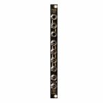
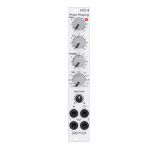
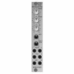
Doepfer A-101-8 Photo Phasing 8-Stage Phase Shifter Module (silver) (phase shifter/effect synth module)
Cat: 945411 Rel: 13 Jun 23
An eight stage phase shifter module in 4HP.
Notes: Module A-101-8 is a 8-stage phase shifter which uses light-sensitive resistors (LDR) and is a replica of the Compact Phasing A manufactured by the company Schulte in the seventies. The actual phasing circuit is identical to the historic model. Only the illumination control of the LDRs is different: the A-101-8 uses LEDs to illuminate the LDRs, the historic model used incandescent miniature lamps. And the A-101-8 has no built-in LFO but can be controlled by any external control voltage source (e.g. LFO, ADSR, random, Theremin, ribbon controller, sequencer, midi). The phasing offset (i.e. the base value for the phase shifting) and the modulation depth of the external control signal can be adjusted separately. The Compact Phasing A had no offset control but only a depth control for the built-in LFO. Feedback and mixing ratio of the output signal are set by two controls. The audio input is equipped with an attenuator. The module has two audio outputs available (same as the historic model) and a visual display of the phase shifting.
The module has these controls and in/outputs available:
Control Man. : manual control of the phase shift offset (base value)
Control CV: attenuator for the signal applied to the CV socket
Control Feedb.: Feedback or Resonance (similar function as filter resonance/feedback/emphasis)
Control Mix: sets the mixing ratio between original and phase shift signal appearing at output 1
fully CCW: only the modified input signal appears at output 1 (see note below *)
center: a mixture between the modified input signal and the phase shift signal appears at output 1, that's the standard position for the classical phasing effect
fully CW: the pure phase shifted signal appears at output 1 (e.g. for vibrato effects)
Control Input Level: attenuator for signal applied to the In socket
Socket In: audio input
Socket CV: control voltage input
Socket Out 1: audio output 1 (mix signal)
Socket Out 2: audio output 2 (modified input signal)
LED: visual control of the phase shift
The module has some peculiarities (same as the historic model):
The input signal is processed at first by a pre-stage which outputs a "modified" input signal (*). This signal is not processed by the phase shift stages but is affected by the feedback setting. Only when feedback is set to zero this signal is identical to the input signal. Otherwise it contains feedback components.
This signal is output on socket Out 2.
When both output sockets Out 1 and Out 2 are used as stereo channels one obtains a spatial stereo sound effect.
The same signals is also used for the CCW position of the mix control. With mix control fully CCW the unmodified signal appears only if the feedback control is set to zero. Otherwise it contains feedback components.
The historic model had two audio inputs: one 5-pin DIN socket and a 1/4" jack socket. The DIN socket was intended for high-level line signals. When the 1/4" jack socket was used the amplification of the pre-stage increased by about 100. The 1/4" jack socket was intended for low level signals (e.g. electric guitars or microphones). For this feature the A-101-8 has an internal jumper that can be used to increase the amplification. As long as the module is used within the A-100 system usually the lower amplification is used to avoid distortion.
The 8 photo resistors and LEDs are assembled within an small lighproof box. In addition the pc boards are made of lighproof black material to avoid interfering light from other modules or the bus board.
Dimensions
4 HP
45 mm deep
Current Draw
30 mA +12V
30 mA -12V
… Read moreThe module has these controls and in/outputs available:
Control Man. : manual control of the phase shift offset (base value)
Control CV: attenuator for the signal applied to the CV socket
Control Feedb.: Feedback or Resonance (similar function as filter resonance/feedback/emphasis)
Control Mix: sets the mixing ratio between original and phase shift signal appearing at output 1
fully CCW: only the modified input signal appears at output 1 (see note below *)
center: a mixture between the modified input signal and the phase shift signal appears at output 1, that's the standard position for the classical phasing effect
fully CW: the pure phase shifted signal appears at output 1 (e.g. for vibrato effects)
Control Input Level: attenuator for signal applied to the In socket
Socket In: audio input
Socket CV: control voltage input
Socket Out 1: audio output 1 (mix signal)
Socket Out 2: audio output 2 (modified input signal)
LED: visual control of the phase shift
The module has some peculiarities (same as the historic model):
The input signal is processed at first by a pre-stage which outputs a "modified" input signal (*). This signal is not processed by the phase shift stages but is affected by the feedback setting. Only when feedback is set to zero this signal is identical to the input signal. Otherwise it contains feedback components.
This signal is output on socket Out 2.
When both output sockets Out 1 and Out 2 are used as stereo channels one obtains a spatial stereo sound effect.
The same signals is also used for the CCW position of the mix control. With mix control fully CCW the unmodified signal appears only if the feedback control is set to zero. Otherwise it contains feedback components.
The historic model had two audio inputs: one 5-pin DIN socket and a 1/4" jack socket. The DIN socket was intended for high-level line signals. When the 1/4" jack socket was used the amplification of the pre-stage increased by about 100. The 1/4" jack socket was intended for low level signals (e.g. electric guitars or microphones). For this feature the A-101-8 has an internal jumper that can be used to increase the amplification. As long as the module is used within the A-100 system usually the lower amplification is used to avoid distortion.
The 8 photo resistors and LEDs are assembled within an small lighproof box. In addition the pc boards are made of lighproof black material to avoid interfering light from other modules or the bus board.
Dimensions
4 HP
45 mm deep
Current Draw
30 mA +12V
30 mA -12V
7 in stock $124.09
Click for better price!
or call +44 20 7424 1960
quote 945411
quote 945411
People also bought...
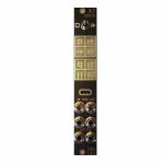
Doepfer A-103 VCF6 18dB Low Pass Filter Module (filter synth module)
Cat: 692504 Rel: 18 Jun 18
18dB low pass filter based on a modified Moog cascade - 8HP
Notes: Module A-103 is a voltage controlled low pass filter with 18dB/octave slope. The circuit is based on a modified transistor ladder (Moog ladder) and is a reproduction of the legendary TB303 filter.
As for the rest the A-103 is identical to the A-120 Moog low pass filter (same controls, inputs/outputs) only the filter sound is different.
… Read moreAs for the rest the A-103 is identical to the A-120 Moog low pass filter (same controls, inputs/outputs) only the filter sound is different.
1 in stock $89.68
Click for better price!
or call +44 20 7424 1960
quote 692504
quote 692504
People also bought...
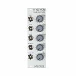
Doepfer A-105-2 24dB Low Pass (SSI-Type) Filter Module (silver) (filter/oscillator synth module)
Cat: 973741 Rel: 14 Nov 23
24dB SSI low pass filter - 4HP.
Notes: Module A-105-2 is a voltage controlled low pass filter with 24dB/octave slope.
It is the successor of the A-105 which had to be discontinued because the obsolete SSM2044 filter circuit. The A-105-2 is based on the SSI2144 which is in turn the successor circuit of the SSM2044. The features of both modules are nearly the same. The main difference is the clearly reduced front panel width of the A-105-2 (4HP instead of 8HP) and the associated changes of the controls and sockets positions. In addition the A-105-2 is equipped with 2 audio inputs.
The module has these controls and in/outputs available:
Control Frequ: manual frequency control
Control FCV2: attenuator for the frequency control voltage applied to socket FCV2
Control Q: manual resonance control
Control QCV: attenuator for the resonance control voltage applied to socket QCV
Control Input 1 Level: attenuator for the audio input signal applied to socket Input 1
Socket Input 1: audio input 1 (with attenuator)
Socket Input 2: audio input 2 (without attenuator)
Socket FCV1: frequency control voltage 1 (without attenuator, about 1V/oct scale)
Socket FCV2: frequency control voltage 2 (with attenuator)
Socket QCV: resonance control voltage (with attenuator)
Socket Out: audio output
Technical notes:
Frequency range: about 15Hz ... 15 kHz
Resonance up to self oscillation
Max. input voltage at Input 2 without clipping/distortion: about 15Vpp
Max. output voltage without clipping/distortion: about 15Vpp
The signals of both inputs are mixed before they are processed by the filter. This saves an external mixer for small setups.
Depth: 45 mm
HP : 4
… Read moreIt is the successor of the A-105 which had to be discontinued because the obsolete SSM2044 filter circuit. The A-105-2 is based on the SSI2144 which is in turn the successor circuit of the SSM2044. The features of both modules are nearly the same. The main difference is the clearly reduced front panel width of the A-105-2 (4HP instead of 8HP) and the associated changes of the controls and sockets positions. In addition the A-105-2 is equipped with 2 audio inputs.
The module has these controls and in/outputs available:
Control Frequ: manual frequency control
Control FCV2: attenuator for the frequency control voltage applied to socket FCV2
Control Q: manual resonance control
Control QCV: attenuator for the resonance control voltage applied to socket QCV
Control Input 1 Level: attenuator for the audio input signal applied to socket Input 1
Socket Input 1: audio input 1 (with attenuator)
Socket Input 2: audio input 2 (without attenuator)
Socket FCV1: frequency control voltage 1 (without attenuator, about 1V/oct scale)
Socket FCV2: frequency control voltage 2 (with attenuator)
Socket QCV: resonance control voltage (with attenuator)
Socket Out: audio output
Technical notes:
Frequency range: about 15Hz ... 15 kHz
Resonance up to self oscillation
Max. input voltage at Input 2 without clipping/distortion: about 15Vpp
Max. output voltage without clipping/distortion: about 15Vpp
The signals of both inputs are mixed before they are processed by the filter. This saves an external mixer for small setups.
Depth: 45 mm
HP : 4
2 in stock $104.28
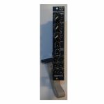
People also bought...
Doepfer A-105-2v 24dB Low Pass (SSI-Type) Filter Vintage Edition Module (black) (filter/oscillator synth module)
Cat: 973745 Rel: 14 Nov 23
24dB SSI low pass filter module - 4HP.
Notes: Module A-105-2V is a voltage controlled low pass filter with 24dB/octave slope.
It is the successor of the A-105 which had to be discontinued because the obsolete SSM2044 filter circuit. The A-105-2 is based on the SSI2144 which is in turn the successor circuit of the SSM2044. The features of both modules are nearly the same. The main difference is the clearly reduced front panel width of the A-105-2 (4HP instead of 8HP) and the associated changes of the controls and sockets positions. In addition the A-105-2 is equipped with 2 audio inputs.
The module has these controls and in/outputs available:
Control Frequ: manual frequency control
Control FCV2: attenuator for the frequency control voltage applied to socket FCV2
Control Q: manual resonance control
Control QCV: attenuator for the resonance control voltage applied to socket QCV
Control Input 1 Level: attenuator for the audio input signal applied to socket Input 1
Socket Input 1: audio input 1 (with attenuator)
Socket Input 2: audio input 2 (without attenuator)
Socket FCV1: frequency control voltage 1 (without attenuator, about 1V/oct scale)
Socket FCV2: frequency control voltage 2 (with attenuator)
Socket QCV: resonance control voltage (with attenuator)
Socket Out: audio output
Technical notes:
Frequency range: about 15Hz ... 15 kHz
Resonance up to self oscillation
Max. input voltage at Input 2 without clipping/distortion: about 15Vpp
Max. output voltage without clipping/distortion: about 15Vpp
The signals of both inputs are mixed before they are processed by the filter. This saves an external mixer for small setups.
Depth: 45 mm
HP : 4
… Read moreIt is the successor of the A-105 which had to be discontinued because the obsolete SSM2044 filter circuit. The A-105-2 is based on the SSI2144 which is in turn the successor circuit of the SSM2044. The features of both modules are nearly the same. The main difference is the clearly reduced front panel width of the A-105-2 (4HP instead of 8HP) and the associated changes of the controls and sockets positions. In addition the A-105-2 is equipped with 2 audio inputs.
The module has these controls and in/outputs available:
Control Frequ: manual frequency control
Control FCV2: attenuator for the frequency control voltage applied to socket FCV2
Control Q: manual resonance control
Control QCV: attenuator for the resonance control voltage applied to socket QCV
Control Input 1 Level: attenuator for the audio input signal applied to socket Input 1
Socket Input 1: audio input 1 (with attenuator)
Socket Input 2: audio input 2 (without attenuator)
Socket FCV1: frequency control voltage 1 (without attenuator, about 1V/oct scale)
Socket FCV2: frequency control voltage 2 (with attenuator)
Socket QCV: resonance control voltage (with attenuator)
Socket Out: audio output
Technical notes:
Frequency range: about 15Hz ... 15 kHz
Resonance up to self oscillation
Max. input voltage at Input 2 without clipping/distortion: about 15Vpp
Max. output voltage without clipping/distortion: about 15Vpp
The signals of both inputs are mixed before they are processed by the filter. This saves an external mixer for small setups.
Depth: 45 mm
HP : 4
1 in stock $112.61
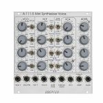
People also bought...
Doepfer A-111-5 Mini Synthesiser Voice Module (silver) (envelope generator/filter/LFO/oscillator/VCA/synth voice synth module)
Cat: 785445 Rel: 10 Sep 20
A complete monophonic synthesiser module (modular version of Dark Energy).
Notes: A fully modular, Eurorack-format version of the excellent Dark Energy synth, the A-111-5 offers VCO, VCF, LFOs, VCA and envelope generator in a compact format. Brilliant value for a starter system.
Supplier's Notes:
Module A-111-5 is a complete monophonic synthesizer module that includes these components (modular version of Dark Energy):
VCO
Manual tune control (with an internal jumper the range can be set to ~ +/-1 half an octave or ~ +/-2.5 octaves)
Range switch -1 / 0 / +1 octave
Frequency range about 10Hz ... 12kHz - FM (frequency modulation) control with modulation source switch (LFO1 / off / ADSR)
Manual pulsewidth control for rectangle waveform
PWM control with modulation source switch (LFO2 / off / ADSR)
Waveform switch (sawtooth / off / triangle)
The sum of the waveform chosen by this switch and the rectangle is fed into the VCF (to turn the rectangle off the PW control has to be set fully CCW)
External CV input for VCO frequency (1V/octave)
External CV input for external PWM of the rectangle - internal CV input for frequency (1V/octave) connected to the A-100 bus via jumper, the jumper can be used to interrupt this internal connection if not wanted
VCF
24 dB low pass
~ 12 octaves frequency range
Manual frequency control
Tracking switch half - off - full (internally connected to the external frequency CV input of the VCO, i.e. the VCF tracks to the VCO if the switch is set to "half" or "full" position)
XM: exponential FM (frequency modulation) control with modulation source switch (LFO2 / off / ADSR)
LM: linear FM (frequency modulation) control to modulate the VCF by the triangle of the VCO in a linear (!) manner
Manual resonance control (up to self oscillation)
External audio input (this signal is added to the VCO signal)
External CV input for filter frequency - 1V/octave tracking for usage of the VCF as a sine wave oscillator (not as precise as the VCO but much better than most of the other filters)
VCA
Manual amplitude control
AM (amplitude modulation) control with modulation source switch (LFO1 / off / ADSR)
External CV input for VCA amplitude - special control scale: exponential scale in the range from about -20dB to -80/90dB, linear scale from about -20dB to 0dB (Remark: this special control scale results in a loudness behaviour that is a bit different from pure linear or exponential VCA)
LFO1 and LFO2
Manual frequency control
Waveform switch (triangle / off / rectangle)
Range switch (low, audio, medium) - LED display (dual green/red color for positive/negative share of the signal)
The inverted LFO1 signal is available as an additional socket (to use the LFO1 signal for external modules)
An internal jumper can be used to select between the LFO1 signal or the inverted LFO1 signal
ADSR
Manual controls for Attack, Decay, Sustain, Release
Range switch (long, short, medium) - blue LED display
ADSR signal is available as an additional socket (to use the ADSR signal for external modules)
Gate input connected to the A-100 bus via jumper, the jumper can be used to interrupt this internal connection if not wanted
Remarks:
As the LFO frequencies can go up to moderate audio range (~ 5kHz) even audio FM effects of VCO (pitch and pulsewidth), VCF and ADSR are possible.
If the VCO is turned off (waveform switch = center position, pulsewidth control = fully CCW) and the VCF resonance is set to maximum the module can be used as a sine oscillator. The sine can be modulated in a linear manner from the triangle wave of the VCO and by LFO2 in an exponential manner at the same time !
From the factory the socket labelled "LFO1" outputs the inverted LFO1 signal. But as the module has several internal pin headers available even another signal may appear at this socket by changing the internal module patch. These six pin headers are available: LFO1 output, LFO2 output, ADSR output, inverter input, inverter output, output socket. The internal default patch is LFO1 -> inverter input, inverter output -> output socket (i.e. socket = inverted LFO1). But even another signal can be patched to this socket (e.g. inverted ADSR, non-inverted LFO1, inverted or non-inverted LFO2). It is also possible to add a blind panel next to the A-111-5 with a couple of sockets that are connected to the corresponding pins of the A-111-5 pc board. The in- and outputs of the VCO, VCF and VCA are not available as pin headers because the VCO, VCF and VCA are internally connected in the circuit which is used in this module.
… Read moreSupplier's Notes:
Module A-111-5 is a complete monophonic synthesizer module that includes these components (modular version of Dark Energy):
VCO
Manual tune control (with an internal jumper the range can be set to ~ +/-1 half an octave or ~ +/-2.5 octaves)
Range switch -1 / 0 / +1 octave
Frequency range about 10Hz ... 12kHz - FM (frequency modulation) control with modulation source switch (LFO1 / off / ADSR)
Manual pulsewidth control for rectangle waveform
PWM control with modulation source switch (LFO2 / off / ADSR)
Waveform switch (sawtooth / off / triangle)
The sum of the waveform chosen by this switch and the rectangle is fed into the VCF (to turn the rectangle off the PW control has to be set fully CCW)
External CV input for VCO frequency (1V/octave)
External CV input for external PWM of the rectangle - internal CV input for frequency (1V/octave) connected to the A-100 bus via jumper, the jumper can be used to interrupt this internal connection if not wanted
VCF
24 dB low pass
~ 12 octaves frequency range
Manual frequency control
Tracking switch half - off - full (internally connected to the external frequency CV input of the VCO, i.e. the VCF tracks to the VCO if the switch is set to "half" or "full" position)
XM: exponential FM (frequency modulation) control with modulation source switch (LFO2 / off / ADSR)
LM: linear FM (frequency modulation) control to modulate the VCF by the triangle of the VCO in a linear (!) manner
Manual resonance control (up to self oscillation)
External audio input (this signal is added to the VCO signal)
External CV input for filter frequency - 1V/octave tracking for usage of the VCF as a sine wave oscillator (not as precise as the VCO but much better than most of the other filters)
VCA
Manual amplitude control
AM (amplitude modulation) control with modulation source switch (LFO1 / off / ADSR)
External CV input for VCA amplitude - special control scale: exponential scale in the range from about -20dB to -80/90dB, linear scale from about -20dB to 0dB (Remark: this special control scale results in a loudness behaviour that is a bit different from pure linear or exponential VCA)
LFO1 and LFO2
Manual frequency control
Waveform switch (triangle / off / rectangle)
Range switch (low, audio, medium) - LED display (dual green/red color for positive/negative share of the signal)
The inverted LFO1 signal is available as an additional socket (to use the LFO1 signal for external modules)
An internal jumper can be used to select between the LFO1 signal or the inverted LFO1 signal
ADSR
Manual controls for Attack, Decay, Sustain, Release
Range switch (long, short, medium) - blue LED display
ADSR signal is available as an additional socket (to use the ADSR signal for external modules)
Gate input connected to the A-100 bus via jumper, the jumper can be used to interrupt this internal connection if not wanted
Remarks:
As the LFO frequencies can go up to moderate audio range (~ 5kHz) even audio FM effects of VCO (pitch and pulsewidth), VCF and ADSR are possible.
If the VCO is turned off (waveform switch = center position, pulsewidth control = fully CCW) and the VCF resonance is set to maximum the module can be used as a sine oscillator. The sine can be modulated in a linear manner from the triangle wave of the VCO and by LFO2 in an exponential manner at the same time !
From the factory the socket labelled "LFO1" outputs the inverted LFO1 signal. But as the module has several internal pin headers available even another signal may appear at this socket by changing the internal module patch. These six pin headers are available: LFO1 output, LFO2 output, ADSR output, inverter input, inverter output, output socket. The internal default patch is LFO1 -> inverter input, inverter output -> output socket (i.e. socket = inverted LFO1). But even another signal can be patched to this socket (e.g. inverted ADSR, non-inverted LFO1, inverted or non-inverted LFO2). It is also possible to add a blind panel next to the A-111-5 with a couple of sockets that are connected to the corresponding pins of the A-111-5 pc board. The in- and outputs of the VCO, VCF and VCA are not available as pin headers because the VCO, VCF and VCA are internally connected in the circuit which is used in this module.
1 in stock $279.48
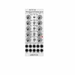
People also bought...
Doepfer A-111-6 Miniature Synthesiser Voice Slim Line Series Module (silver) (synth voice synth module)
Cat: 731937 Rel: 15 Nov 19
Complete miniature monophonic synthesiser module - 10HP
Notes: VCO:
- Tune: manual tune control (with an internal jumper the range can be set to ~ +/-1 half an octave or ~ +/-2.5 octaves)
- Oct: range switch -1 / 0 / +1 octave
- Mod: modulation depth (attenuator wired to the Mod. socket)
- Dest: switch that is used to address the modulation to frequency modulation (position FM) or pulsewidth modulation (positon PM), in centre positon no modulation
- PW: manual pulsewidth control for rectangle waveform, PW can be also modulated by the Mod. input as mentioned above
- Wave: waveform switch (sawtooth / off / triangle), the sum of the waveform chosen by this switch and the rectangle is fed into the VCF (to turn the rectangle off the PW control has to be set fully CCW or fully CW)
- 1V/Oct. (socket): external CV input for VCO frequency (1V/octave)
- Access to internal bus CV (via jumper, optional, please remove the bus jumper if this feature is not used to avoid unwanted frequency modulation as then the unused CV line of the bus works as a kind of antenna)
- Triangle core VCO, frequency range about 32Hz ... 8kHz
Balance unit:
- The balance unit is made of two VCAs which are controlled by the sum of manual Balance control and the balance CV input in the opposite direction.
- The audio input of VCA1 is hard-wired to the VCO output, audio input 2 is connected to the socket Ext.In.
- The output of the balance unit is used as audio input for the VCF
- Bal.: manual balance control, fully CCW the internal VCO is used, fully CW the external signal (Ext.In) is used, at centre position both signals have about the same level
- CV Bal.: CV input for balance (range about 0...+5V)
- Ext. In: external audio input for VCA2, about 5 Vpp level required for similar loudness as the internal VCO
- This socket is normalled to the internal VCO suboctave f/2 signal (rectangle with half the frequency), if no external signal is applied the suboctave signal is used as the second signal for the balance unit
VCF:
- 24 dB low pass
- Frq: manual frequency control
- FM1: frequency modulation depth (attenuator wired to the VCF FM1 socket, the socket is normalled to the internal Envelope signal and then FM1 controls the modulation depth of the internal envelope applied to the filter)
- FM2 (socket) : second CV input for VCF without attenuator (about 1V/octave), can be used e.g. for VCF tracking by connecting the same CV which is used also for the VCO frequency
- Res: manual resonance control (up to self oscillation)
- If the VCO is turned off (waveform switch = centre position, pulsewidth control = fully CCW or CW) and the VCF resonance is set to maximum the module can be used as a sine oscillator, the tracking at socket VCF FM2 is about 1V/octave (not as precise as the VCO but much better than most other filters)
- ~ 11 octaves frequency range (~ 10 Hz ... 20kHz)
VCA:
- Gain: manual amplitude control (initial gain), can be used to open the VCA without envelope signal
- VCA (switch): used to switch between gate and envelope as control signal for the VCA, in centre position the VCA is not controlled by envelope or gate
- Note: when gate is used the VCA is controlled directly by the gate signal (i.e. hard on/off), this may lead to clicking noise under certain conditions (especially with low VCO/VCF frequencies)
- Special control scale: exponential scale in the range from about -20dB to -80/90dB, linear scale from about -20dB to 0dB
- Remark: this special control scale results in a loudness behaviour that is a bit different from pure linear or exponential VCAs
- Out: audio output of the module (= VCA output)
Envelope:
- Gate (socket): Gate input (min. +5V), can be normalled to the bus gate signal by means of a jumper
- Att: manual control for Attack
- D/R: manual control for Decay/Release
- Env. (switch): used to switch between A/D, ADSR and A/R mode of the envelope generator, in centre position (ADSR) the sustain level is fixed to about 50%
- Envelope (socket): envelope output (about +10V)
- CVT (socket): CV input for time control, by means of two internal jumpers one can select which time parameters are controlled by the CVT input (e.g. A only or D/R only or A/D/R) and in which direction (i.e. if an increasing CVT shortens or stretches the time parameter in question)
- Envelope LED display
- Attack time range: ~ 1ms ... 5 sec (can be extended by using the CVT input)
- Decay/Release time range: ~ 1ms ... 15 sec (can be extended by using the CVT input)
… Read more- Tune: manual tune control (with an internal jumper the range can be set to ~ +/-1 half an octave or ~ +/-2.5 octaves)
- Oct: range switch -1 / 0 / +1 octave
- Mod: modulation depth (attenuator wired to the Mod. socket)
- Dest: switch that is used to address the modulation to frequency modulation (position FM) or pulsewidth modulation (positon PM), in centre positon no modulation
- PW: manual pulsewidth control for rectangle waveform, PW can be also modulated by the Mod. input as mentioned above
- Wave: waveform switch (sawtooth / off / triangle), the sum of the waveform chosen by this switch and the rectangle is fed into the VCF (to turn the rectangle off the PW control has to be set fully CCW or fully CW)
- 1V/Oct. (socket): external CV input for VCO frequency (1V/octave)
- Access to internal bus CV (via jumper, optional, please remove the bus jumper if this feature is not used to avoid unwanted frequency modulation as then the unused CV line of the bus works as a kind of antenna)
- Triangle core VCO, frequency range about 32Hz ... 8kHz
Balance unit:
- The balance unit is made of two VCAs which are controlled by the sum of manual Balance control and the balance CV input in the opposite direction.
- The audio input of VCA1 is hard-wired to the VCO output, audio input 2 is connected to the socket Ext.In.
- The output of the balance unit is used as audio input for the VCF
- Bal.: manual balance control, fully CCW the internal VCO is used, fully CW the external signal (Ext.In) is used, at centre position both signals have about the same level
- CV Bal.: CV input for balance (range about 0...+5V)
- Ext. In: external audio input for VCA2, about 5 Vpp level required for similar loudness as the internal VCO
- This socket is normalled to the internal VCO suboctave f/2 signal (rectangle with half the frequency), if no external signal is applied the suboctave signal is used as the second signal for the balance unit
VCF:
- 24 dB low pass
- Frq: manual frequency control
- FM1: frequency modulation depth (attenuator wired to the VCF FM1 socket, the socket is normalled to the internal Envelope signal and then FM1 controls the modulation depth of the internal envelope applied to the filter)
- FM2 (socket) : second CV input for VCF without attenuator (about 1V/octave), can be used e.g. for VCF tracking by connecting the same CV which is used also for the VCO frequency
- Res: manual resonance control (up to self oscillation)
- If the VCO is turned off (waveform switch = centre position, pulsewidth control = fully CCW or CW) and the VCF resonance is set to maximum the module can be used as a sine oscillator, the tracking at socket VCF FM2 is about 1V/octave (not as precise as the VCO but much better than most other filters)
- ~ 11 octaves frequency range (~ 10 Hz ... 20kHz)
VCA:
- Gain: manual amplitude control (initial gain), can be used to open the VCA without envelope signal
- VCA (switch): used to switch between gate and envelope as control signal for the VCA, in centre position the VCA is not controlled by envelope or gate
- Note: when gate is used the VCA is controlled directly by the gate signal (i.e. hard on/off), this may lead to clicking noise under certain conditions (especially with low VCO/VCF frequencies)
- Special control scale: exponential scale in the range from about -20dB to -80/90dB, linear scale from about -20dB to 0dB
- Remark: this special control scale results in a loudness behaviour that is a bit different from pure linear or exponential VCAs
- Out: audio output of the module (= VCA output)
Envelope:
- Gate (socket): Gate input (min. +5V), can be normalled to the bus gate signal by means of a jumper
- Att: manual control for Attack
- D/R: manual control for Decay/Release
- Env. (switch): used to switch between A/D, ADSR and A/R mode of the envelope generator, in centre position (ADSR) the sustain level is fixed to about 50%
- Envelope (socket): envelope output (about +10V)
- CVT (socket): CV input for time control, by means of two internal jumpers one can select which time parameters are controlled by the CVT input (e.g. A only or D/R only or A/D/R) and in which direction (i.e. if an increasing CVT shortens or stretches the time parameter in question)
- Envelope LED display
- Attack time range: ~ 1ms ... 5 sec (can be extended by using the CVT input)
- Decay/Release time range: ~ 1ms ... 15 sec (can be extended by using the CVT input)
1 in stock $175.18
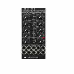
People also bought...
Doepfer A-111-6v Miniature Synthesiser Voice Vintage Edition Module (black) (synth voice synth module)
Cat: 749811 Rel: 15 Nov 19
Complete miniature monophonic synthesiser module - 10HP
Notes: VCO:
- Tune: manual tune control (with an internal jumper the range can be set to ~ +/-1 half an octave or ~ +/-2.5 octaves)
- Oct: range switch -1 / 0 / +1 octave
- Mod: modulation depth (attenuator wired to the Mod. socket)
- Dest: switch that is used to address the modulation to frequency modulation (position FM) or pulsewidth modulation (positon PM), in centre positon no modulation
- PW: manual pulsewidth control for rectangle waveform, PW can be also modulated by the Mod. input as mentioned above
- Wave: waveform switch (sawtooth / off / triangle), the sum of the waveform chosen by this switch and the rectangle is fed into the VCF (to turn the rectangle off the PW control has to be set fully CCW or fully CW)
- 1V/Oct. (socket): external CV input for VCO frequency (1V/octave)
- Access to internal bus CV (via jumper, optional, please remove the bus jumper if this feature is not used to avoid unwanted frequency modulation as then the unused CV line of the bus works as a kind of antenna)
- Triangle core VCO, frequency range about 32Hz ... 8kHz
Balance unit:
- The balance unit is made of two VCAs which are controlled by the sum of manual Balance control and the balance CV input in the opposite direction.
- The audio input of VCA1 is hard-wired to the VCO output, audio input 2 is connected to the socket Ext.In.
- The output of the balance unit is used as audio input for the VCF
- Bal.: manual balance control, fully CCW the internal VCO is used, fully CW the external signal (Ext.In) is used, at centre position both signals have about the same level
- CV Bal.: CV input for balance (range about 0...+5V)
- Ext. In: external audio input for VCA2, about 5 Vpp level required for similar loudness as the internal VCO
- This socket is normalled to the internal VCO suboctave f/2 signal (rectangle with half the frequency), if no external signal is applied the suboctave signal is used as the second signal for the balance unit
VCF:
- 24 dB low pass
- Frq: manual frequency control
- FM1: frequency modulation depth (attenuator wired to the VCF FM1 socket, the socket is normalled to the internal Envelope signal and then FM1 controls the modulation depth of the internal envelope applied to the filter)
- FM2 (socket) : second CV input for VCF without attenuator (about 1V/octave), can be used e.g. for VCF tracking by connecting the same CV which is used also for the VCO frequency
- Res: manual resonance control (up to self oscillation)
- If the VCO is turned off (waveform switch = centre position, pulsewidth control = fully CCW or CW) and the VCF resonance is set to maximum the module can be used as a sine oscillator, the tracking at socket VCF FM2 is about 1V/octave (not as precise as the VCO but much better than most other filters)
- ~ 11 octaves frequency range (~ 10 Hz ... 20kHz)
VCA:
- Gain: manual amplitude control (initial gain), can be used to open the VCA without envelope signal
- VCA (switch): used to switch between gate and envelope as control signal for the VCA, in centre position the VCA is not controlled by envelope or gate
- Note: when gate is used the VCA is controlled directly by the gate signal (i.e. hard on/off), this may lead to clicking noise under certain conditions (especially with low VCO/VCF frequencies)
- Special control scale: exponential scale in the range from about -20dB to -80/90dB, linear scale from about -20dB to 0dB
- Remark: this special control scale results in a loudness behaviour that is a bit different from pure linear or exponential VCAs
- Out: audio output of the module (= VCA output)
Envelope:
- Gate (socket): Gate input (min. +5V), can be normalled to the bus gate signal by means of a jumper
- Att: manual control for Attack
- D/R: manual control for Decay/Release
- Env. (switch): used to switch between A/D, ADSR and A/R mode of the envelope generator, in centre position (ADSR) the sustain level is fixed to about 50%
- Envelope (socket): envelope output (about +10V)
- CVT (socket): CV input for time control, by means of two internal jumpers one can select which time parameters are controlled by the CVT input (e.g. A only or D/R only or A/D/R) and in which direction (i.e. if an increasing CVT shortens or stretches the time parameter in question)
- Envelope LED display
- Attack time range: ~ 1ms ... 5 sec (can be extended by using the CVT input)
- Decay/Release time range: ~ 1ms ... 15 sec (can be extended by using the CVT input)
… Read more- Tune: manual tune control (with an internal jumper the range can be set to ~ +/-1 half an octave or ~ +/-2.5 octaves)
- Oct: range switch -1 / 0 / +1 octave
- Mod: modulation depth (attenuator wired to the Mod. socket)
- Dest: switch that is used to address the modulation to frequency modulation (position FM) or pulsewidth modulation (positon PM), in centre positon no modulation
- PW: manual pulsewidth control for rectangle waveform, PW can be also modulated by the Mod. input as mentioned above
- Wave: waveform switch (sawtooth / off / triangle), the sum of the waveform chosen by this switch and the rectangle is fed into the VCF (to turn the rectangle off the PW control has to be set fully CCW or fully CW)
- 1V/Oct. (socket): external CV input for VCO frequency (1V/octave)
- Access to internal bus CV (via jumper, optional, please remove the bus jumper if this feature is not used to avoid unwanted frequency modulation as then the unused CV line of the bus works as a kind of antenna)
- Triangle core VCO, frequency range about 32Hz ... 8kHz
Balance unit:
- The balance unit is made of two VCAs which are controlled by the sum of manual Balance control and the balance CV input in the opposite direction.
- The audio input of VCA1 is hard-wired to the VCO output, audio input 2 is connected to the socket Ext.In.
- The output of the balance unit is used as audio input for the VCF
- Bal.: manual balance control, fully CCW the internal VCO is used, fully CW the external signal (Ext.In) is used, at centre position both signals have about the same level
- CV Bal.: CV input for balance (range about 0...+5V)
- Ext. In: external audio input for VCA2, about 5 Vpp level required for similar loudness as the internal VCO
- This socket is normalled to the internal VCO suboctave f/2 signal (rectangle with half the frequency), if no external signal is applied the suboctave signal is used as the second signal for the balance unit
VCF:
- 24 dB low pass
- Frq: manual frequency control
- FM1: frequency modulation depth (attenuator wired to the VCF FM1 socket, the socket is normalled to the internal Envelope signal and then FM1 controls the modulation depth of the internal envelope applied to the filter)
- FM2 (socket) : second CV input for VCF without attenuator (about 1V/octave), can be used e.g. for VCF tracking by connecting the same CV which is used also for the VCO frequency
- Res: manual resonance control (up to self oscillation)
- If the VCO is turned off (waveform switch = centre position, pulsewidth control = fully CCW or CW) and the VCF resonance is set to maximum the module can be used as a sine oscillator, the tracking at socket VCF FM2 is about 1V/octave (not as precise as the VCO but much better than most other filters)
- ~ 11 octaves frequency range (~ 10 Hz ... 20kHz)
VCA:
- Gain: manual amplitude control (initial gain), can be used to open the VCA without envelope signal
- VCA (switch): used to switch between gate and envelope as control signal for the VCA, in centre position the VCA is not controlled by envelope or gate
- Note: when gate is used the VCA is controlled directly by the gate signal (i.e. hard on/off), this may lead to clicking noise under certain conditions (especially with low VCO/VCF frequencies)
- Special control scale: exponential scale in the range from about -20dB to -80/90dB, linear scale from about -20dB to 0dB
- Remark: this special control scale results in a loudness behaviour that is a bit different from pure linear or exponential VCAs
- Out: audio output of the module (= VCA output)
Envelope:
- Gate (socket): Gate input (min. +5V), can be normalled to the bus gate signal by means of a jumper
- Att: manual control for Attack
- D/R: manual control for Decay/Release
- Env. (switch): used to switch between A/D, ADSR and A/R mode of the envelope generator, in centre position (ADSR) the sustain level is fixed to about 50%
- Envelope (socket): envelope output (about +10V)
- CVT (socket): CV input for time control, by means of two internal jumpers one can select which time parameters are controlled by the CVT input (e.g. A only or D/R only or A/D/R) and in which direction (i.e. if an increasing CVT shortens or stretches the time parameter in question)
- Envelope LED display
- Attack time range: ~ 1ms ... 5 sec (can be extended by using the CVT input)
- Decay/Release time range: ~ 1ms ... 15 sec (can be extended by using the CVT input)
3 in stock $183.53

People also bought...
Doepfer A-111-6v Miniature Synthesiser Voice Vintage Edition Module (black) (B-STOCK) (synth voice synth module)
Cat: 970408 Rel: 01 Jan 90
B-STOCK: Slight dent om the edge, otherwise in perfect condition
Notes: ***B-STOCK: Slight dent om the edge, otherwise in perfect condition***
VCO:
- Tune: manual tune control (with an internal jumper the range can be set to ~ +/-1 half an octave or ~ +/-2.5 octaves)
- Oct: range switch -1 / 0 / +1 octave
- Mod: modulation depth (attenuator wired to the Mod. socket)
- Dest: switch that is used to address the modulation to frequency modulation (position FM) or pulsewidth modulation (positon PM), in centre positon no modulation
- PW: manual pulsewidth control for rectangle waveform, PW can be also modulated by the Mod. input as mentioned above
- Wave: waveform switch (sawtooth / off / triangle), the sum of the waveform chosen by this switch and the rectangle is fed into the VCF (to turn the rectangle off the PW control has to be set fully CCW or fully CW)
- 1V/Oct. (socket): external CV input for VCO frequency (1V/octave)
- Access to internal bus CV (via jumper, optional, please remove the bus jumper if this feature is not used to avoid unwanted frequency modulation as then the unused CV line of the bus works as a kind of antenna)
- Triangle core VCO, frequency range about 32Hz ... 8kHz
Balance unit:
- The balance unit is made of two VCAs which are controlled by the sum of manual Balance control and the balance CV input in the opposite direction.
- The audio input of VCA1 is hard-wired to the VCO output, audio input 2 is connected to the socket Ext.In.
- The output of the balance unit is used as audio input for the VCF
- Bal.: manual balance control, fully CCW the internal VCO is used, fully CW the external signal (Ext.In) is used, at centre position both signals have about the same level
- CV Bal.: CV input for balance (range about 0...+5V)
- Ext. In: external audio input for VCA2, about 5 Vpp level required for similar loudness as the internal VCO
- This socket is normalled to the internal VCO suboctave f/2 signal (rectangle with half the frequency), if no external signal is applied the suboctave signal is used as the second signal for the balance unit
VCF:
- 24 dB low pass
- Frq: manual frequency control
- FM1: frequency modulation depth (attenuator wired to the VCF FM1 socket, the socket is normalled to the internal Envelope signal and then FM1 controls the modulation depth of the internal envelope applied to the filter)
- FM2 (socket) : second CV input for VCF without attenuator (about 1V/octave), can be used e.g. for VCF tracking by connecting the same CV which is used also for the VCO frequency
- Res: manual resonance control (up to self oscillation)
- If the VCO is turned off (waveform switch = centre position, pulsewidth control = fully CCW or CW) and the VCF resonance is set to maximum the module can be used as a sine oscillator, the tracking at socket VCF FM2 is about 1V/octave (not as precise as the VCO but much better than most other filters)
- ~ 11 octaves frequency range (~ 10 Hz ... 20kHz)
VCA:
- Gain: manual amplitude control (initial gain), can be used to open the VCA without envelope signal
- VCA (switch): used to switch between gate and envelope as control signal for the VCA, in centre position the VCA is not controlled by envelope or gate
- Note: when gate is used the VCA is controlled directly by the gate signal (i.e. hard on/off), this may lead to clicking noise under certain conditions (especially with low VCO/VCF frequencies)
- Special control scale: exponential scale in the range from about -20dB to -80/90dB, linear scale from about -20dB to 0dB
- Remark: this special control scale results in a loudness behaviour that is a bit different from pure linear or exponential VCAs
- Out: audio output of the module (= VCA output)
Envelope:
- Gate (socket): Gate input (min. +5V), can be normalled to the bus gate signal by means of a jumper
- Att: manual control for Attack
- D/R: manual control for Decay/Release
- Env. (switch): used to switch between A/D, ADSR and A/R mode of the envelope generator, in centre position (ADSR) the sustain level is fixed to about 50%
- Envelope (socket): envelope output (about +10V)
- CVT (socket): CV input for time control, by means of two internal jumpers one can select which time parameters are controlled by the CVT input (e.g. A only or D/R only or A/D/R) and in which direction (i.e. if an increasing CVT shortens or stretches the time parameter in question)
- Envelope LED display
- Attack time range: ~ 1ms ... 5 sec (can be extended by using the CVT input)
- Decay/Release time range: ~ 1ms ... 15 sec (can be extended by using the CVT input)
… Read moreVCO:
- Tune: manual tune control (with an internal jumper the range can be set to ~ +/-1 half an octave or ~ +/-2.5 octaves)
- Oct: range switch -1 / 0 / +1 octave
- Mod: modulation depth (attenuator wired to the Mod. socket)
- Dest: switch that is used to address the modulation to frequency modulation (position FM) or pulsewidth modulation (positon PM), in centre positon no modulation
- PW: manual pulsewidth control for rectangle waveform, PW can be also modulated by the Mod. input as mentioned above
- Wave: waveform switch (sawtooth / off / triangle), the sum of the waveform chosen by this switch and the rectangle is fed into the VCF (to turn the rectangle off the PW control has to be set fully CCW or fully CW)
- 1V/Oct. (socket): external CV input for VCO frequency (1V/octave)
- Access to internal bus CV (via jumper, optional, please remove the bus jumper if this feature is not used to avoid unwanted frequency modulation as then the unused CV line of the bus works as a kind of antenna)
- Triangle core VCO, frequency range about 32Hz ... 8kHz
Balance unit:
- The balance unit is made of two VCAs which are controlled by the sum of manual Balance control and the balance CV input in the opposite direction.
- The audio input of VCA1 is hard-wired to the VCO output, audio input 2 is connected to the socket Ext.In.
- The output of the balance unit is used as audio input for the VCF
- Bal.: manual balance control, fully CCW the internal VCO is used, fully CW the external signal (Ext.In) is used, at centre position both signals have about the same level
- CV Bal.: CV input for balance (range about 0...+5V)
- Ext. In: external audio input for VCA2, about 5 Vpp level required for similar loudness as the internal VCO
- This socket is normalled to the internal VCO suboctave f/2 signal (rectangle with half the frequency), if no external signal is applied the suboctave signal is used as the second signal for the balance unit
VCF:
- 24 dB low pass
- Frq: manual frequency control
- FM1: frequency modulation depth (attenuator wired to the VCF FM1 socket, the socket is normalled to the internal Envelope signal and then FM1 controls the modulation depth of the internal envelope applied to the filter)
- FM2 (socket) : second CV input for VCF without attenuator (about 1V/octave), can be used e.g. for VCF tracking by connecting the same CV which is used also for the VCO frequency
- Res: manual resonance control (up to self oscillation)
- If the VCO is turned off (waveform switch = centre position, pulsewidth control = fully CCW or CW) and the VCF resonance is set to maximum the module can be used as a sine oscillator, the tracking at socket VCF FM2 is about 1V/octave (not as precise as the VCO but much better than most other filters)
- ~ 11 octaves frequency range (~ 10 Hz ... 20kHz)
VCA:
- Gain: manual amplitude control (initial gain), can be used to open the VCA without envelope signal
- VCA (switch): used to switch between gate and envelope as control signal for the VCA, in centre position the VCA is not controlled by envelope or gate
- Note: when gate is used the VCA is controlled directly by the gate signal (i.e. hard on/off), this may lead to clicking noise under certain conditions (especially with low VCO/VCF frequencies)
- Special control scale: exponential scale in the range from about -20dB to -80/90dB, linear scale from about -20dB to 0dB
- Remark: this special control scale results in a loudness behaviour that is a bit different from pure linear or exponential VCAs
- Out: audio output of the module (= VCA output)
Envelope:
- Gate (socket): Gate input (min. +5V), can be normalled to the bus gate signal by means of a jumper
- Att: manual control for Attack
- D/R: manual control for Decay/Release
- Env. (switch): used to switch between A/D, ADSR and A/R mode of the envelope generator, in centre position (ADSR) the sustain level is fixed to about 50%
- Envelope (socket): envelope output (about +10V)
- CVT (socket): CV input for time control, by means of two internal jumpers one can select which time parameters are controlled by the CVT input (e.g. A only or D/R only or A/D/R) and in which direction (i.e. if an increasing CVT shortens or stretches the time parameter in question)
- Envelope LED display
- Attack time range: ~ 1ms ... 5 sec (can be extended by using the CVT input)
- Decay/Release time range: ~ 1ms ... 15 sec (can be extended by using the CVT input)
1 in stock $165.81
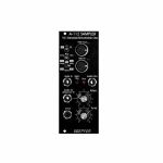
People also bought...
Doepfer A-112v Sampler VC Sampler & Wavetable Oscillator Vintage Edition Module (black) (delay/digital/oscillator/sampling synth module)
Cat: 671610 Rel: 29 Nov 17
Combined module of voltage-controlled 8-bit sampler & wavetable oscillator - vintage edition, 10HP
Notes: Module A-112 is the combination of a voltage controlled 8 Bit Sampler and a wavetable oscillator. On top of it the module is able to generate some special effects. A-112 was designed as an additional sound source with the typical sounds of the early 8 bit samplers and is not comparable with the modern polyphonic MIDI samplers available on the market.
Sampling mode: 8 bit audio resolution, 128kB memory in 2 banks 64kB each (equivalent to 2 seconds of sampling time for each bank with 32 kHz sampling rate), audio input with attenuator, overload display in record mode (gate LED), possibility of MIDI Dump to store sounds in a computer via MIDI, non-volatile memory for the 2 samples in the module, manual tune control for adjustment of sampling rate for record and play, CV input (~ 1V/Oct), both manual tune and CV determine the sampling rate respectively the pitch (pitch range is 5 octaves), gate input (not a trigger: the sample starts at the positive edge of the gate signal and is played as long as gate is high or until the end of the sample is reached), manual Gate button, non-filtered audio output (thus quantizing noise can be used as an element of the sound intentionally).
Wavetable mode: special appearance of the sampling mode when playing a sample, the audio input is now used as a second control voltage input for moving through the sample in 256 byte wide loops (wavetables). The control voltage required to move through all wavetables applied to the input "Wave CV In" is in the range -2.5V (wavetable 1) ... 0V (wavetable 127) ... +2.5V (wavetable 256) when control "Atten." is set fully clockwise. To achieve the typical wavetable oscillator sounds the sampling memory must contain corresponding wavetable data (e.g. loaded via MIDI dump). These data contain a set of wavetables with different harmonic content (e.g. a filter sweep) to get the typical wavetable sound while moving through the tables via CV. But you may also use a "normal" sample and go through the sample with CV to obtain partially amazing sounds never heard before. You may use for example sampled speech and go with CV through the syllables or speech shreds to get really very extreme sounds. An ideal addition for this feature is the Offset/Attenuator module A-183-2 which can be used to adjust the position of the wavetable (Offset) and the modulation depth (Att.). The corresponding jumper of the A-183-2 has to be set to bipolar offset (as the A-112 requires -2.5V...+2.5V to pass through all 256 wavetables). As modulation source an LFO (A-145, A-146, A-147, A-143-3), ADSR (A-140, A-141, A-142, A-143-1/2) or a random voltage (A-118, A-149-1) may be used. Even a ribbon controller (A-198 or R2M), the Theremin module A-178, the Joystick A-174 or the Wheels module A-174-2 are useful to drive through the wavetables.
Effects: Additionally, the module offers - in a way free of charge - some effects like delay, reverse delay, pitch shifting or freeze. But it has to be pointed out that due to the 8 bit audio resolution these effects are not comparable to high quality effect units and should be understand as an extra for nothing. The A-112 is not an effects unit!
The sampling time of the A-112 is about 1...30 seconds corresponding to a sampling frequency range of about 60kHz...2kHz (64kB@60kHz ~ 1 s, 64kB@2kHz ~ 30 s).
Technical note: the module uses a battery for the non-volatile storage of the sampling data. Batteries have a limited lifespan and have to be inspected at least every two years. For details please refer to the FAQ page of our website: Lifespan of rechargeable batteries (used for memory backup).
… Read moreSampling mode: 8 bit audio resolution, 128kB memory in 2 banks 64kB each (equivalent to 2 seconds of sampling time for each bank with 32 kHz sampling rate), audio input with attenuator, overload display in record mode (gate LED), possibility of MIDI Dump to store sounds in a computer via MIDI, non-volatile memory for the 2 samples in the module, manual tune control for adjustment of sampling rate for record and play, CV input (~ 1V/Oct), both manual tune and CV determine the sampling rate respectively the pitch (pitch range is 5 octaves), gate input (not a trigger: the sample starts at the positive edge of the gate signal and is played as long as gate is high or until the end of the sample is reached), manual Gate button, non-filtered audio output (thus quantizing noise can be used as an element of the sound intentionally).
Wavetable mode: special appearance of the sampling mode when playing a sample, the audio input is now used as a second control voltage input for moving through the sample in 256 byte wide loops (wavetables). The control voltage required to move through all wavetables applied to the input "Wave CV In" is in the range -2.5V (wavetable 1) ... 0V (wavetable 127) ... +2.5V (wavetable 256) when control "Atten." is set fully clockwise. To achieve the typical wavetable oscillator sounds the sampling memory must contain corresponding wavetable data (e.g. loaded via MIDI dump). These data contain a set of wavetables with different harmonic content (e.g. a filter sweep) to get the typical wavetable sound while moving through the tables via CV. But you may also use a "normal" sample and go through the sample with CV to obtain partially amazing sounds never heard before. You may use for example sampled speech and go with CV through the syllables or speech shreds to get really very extreme sounds. An ideal addition for this feature is the Offset/Attenuator module A-183-2 which can be used to adjust the position of the wavetable (Offset) and the modulation depth (Att.). The corresponding jumper of the A-183-2 has to be set to bipolar offset (as the A-112 requires -2.5V...+2.5V to pass through all 256 wavetables). As modulation source an LFO (A-145, A-146, A-147, A-143-3), ADSR (A-140, A-141, A-142, A-143-1/2) or a random voltage (A-118, A-149-1) may be used. Even a ribbon controller (A-198 or R2M), the Theremin module A-178, the Joystick A-174 or the Wheels module A-174-2 are useful to drive through the wavetables.
Effects: Additionally, the module offers - in a way free of charge - some effects like delay, reverse delay, pitch shifting or freeze. But it has to be pointed out that due to the 8 bit audio resolution these effects are not comparable to high quality effect units and should be understand as an extra for nothing. The A-112 is not an effects unit!
The sampling time of the A-112 is about 1...30 seconds corresponding to a sampling frequency range of about 60kHz...2kHz (64kB@60kHz ~ 1 s, 64kB@2kHz ~ 30 s).
Technical note: the module uses a battery for the non-volatile storage of the sampling data. Batteries have a limited lifespan and have to be inspected at least every two years. For details please refer to the FAQ page of our website: Lifespan of rechargeable batteries (used for memory backup).
1 in stock $172.05
Click for better price!
or call +44 20 7424 1960
quote 671610
quote 671610
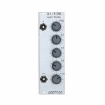
People also bought...
Doepfer A-115 Audio Divider Module (frequency divider synth module)
Cat: 698545 Rel: 15 Aug 18
Fourfold frequency divider for creating up to four sub-octaves - 8HP
Notes: Module A-115 is a four-way frequency divider. The frequency of a signal at the input is halved (half frequency = first sub-octave), quartered (1/4 frequency = second sub-octave), and so on. In this way, the DIVIDER produces four sub-octaves (F/2 down to F/16).
At the output, the A-115 produces a summed mix of the original and the four sub-octaves. There are attenuators to control the amount (i.e. Amplitude) of the original signal and each of the sub-octaves.
Bear in mind that the sub-octaves output by the A-115 are all true square waves. At the output there are always four square waves and the original signal available.
… Read moreAt the output, the A-115 produces a summed mix of the original and the four sub-octaves. There are attenuators to control the amount (i.e. Amplitude) of the original signal and each of the sub-octaves.
Bear in mind that the sub-octaves output by the A-115 are all true square waves. At the output there are always four square waves and the original signal available.
1 in stock $65.69
Click for better price!
or call +44 20 7424 1960
quote 698545
quote 698545
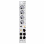
People also bought...
Doepfer A-118-2 Noise/Random/Sample & Hold Slim Line Module (silver) (noise/random/sample & hold module)
Cat: 731938 Rel: 10 Jun 19
Noise, random, sample & hold module - 4HP
Notes: Module A-118-2 is the slim version of module A-118-1 and offers essentially the same features as the A-118-1. But the distances between the controls are smaller and rubberized small-sized knobs are used. In return the front panel has 4 HP only which is half the width of the A-118-1. The module is primarily planned for applications where only limited space is available. The functional difference between A-118-1 and A-118-2 is the additional T&H/S&H unit which is not included in the A-118-1.
The module generates the signals white noise, colored noise, continuous random voltage and stepped random voltage (derived from the continuous random voltage by means of a S&H/T&H unit).
The noise signal is generated 100% analog by amplification of the noise of a transistor. White and colored noise are usually used as audio sources. The random voltages are normally used as control voltages (e.g. for filter frequency or any other voltage controlled parameter).
The A-118-2 gives you the ability to mix the relative amounts of Red (low frequency component) and Blue noise (high frequency component) in the colored noise output.
For the continuous random voltage the rate of change (Rate) and amplitude (Level) of the random voltage can be adjusted. The continuous random voltage is derived from the colored noise signal by low pass filtering. Consequently the settings of the controls for the colored noise (Blue, Red) affect the behavior of the random voltage! A dual color LED (red = positive / yellow = negative output voltage) indicates the continuous random voltage.
The continuous random voltage is used as source for the S&H/T&H unit. The type of operation can be set to S&H (sample and hold) or T&H (track and hold). When T&H is chosen the output signal follows the input signal (= continuous random voltage) as long as the Clock input is "high". As soon as the clock signal changes to "low" the last voltage is stored. When S&H is chosen the input signal (= continuous random voltage) is sampled at the rising edge of the Clock signal.
For the Clock signal a "digital" signal (e.g. Clock, Gate, rectangle output of an LFO) is required. It does not work with slowly changing continuous CV signals. Another dual color LED (red = positive / yellow = negative output voltage) indicates the stepped random voltage.
Controls:
Blue: share of the high frequencies in the the colored noise output
Red: share of the low frequencies in the the colored noise output
Rate: rate of change of the continuous random voltage
Level: amplitude of the continuous random voltage
TH/SH: switches between T&H and S&H
Inputs and outputs:
RND: continuous random voltage output (with LED display)
TH/SH: stepped random voltage output (with LED display)
Clk: Clock input of the S&H/T&H unit
C Noise: colored noise output
W Noise: white noise output
Important notes:
After power on it takes a few minutes until the two noise signals and the random signals are generated. The module is not faulty when after power on the signals do not appear immediately!
The S&H/T&H function is realized by pure analog circuitry (electronic switch followed by a holding capacitor and buffer). Consequently the output voltage drifts a bit in the holding state because the capacitor is discharged by parasitic resistors. The drift depends also upon environmental conditions like humidity or temperature.
Dimensions
4 HP
40 mm deep
Current Draw
20 mA +12V
20 mA -12V
… Read moreThe module generates the signals white noise, colored noise, continuous random voltage and stepped random voltage (derived from the continuous random voltage by means of a S&H/T&H unit).
The noise signal is generated 100% analog by amplification of the noise of a transistor. White and colored noise are usually used as audio sources. The random voltages are normally used as control voltages (e.g. for filter frequency or any other voltage controlled parameter).
The A-118-2 gives you the ability to mix the relative amounts of Red (low frequency component) and Blue noise (high frequency component) in the colored noise output.
For the continuous random voltage the rate of change (Rate) and amplitude (Level) of the random voltage can be adjusted. The continuous random voltage is derived from the colored noise signal by low pass filtering. Consequently the settings of the controls for the colored noise (Blue, Red) affect the behavior of the random voltage! A dual color LED (red = positive / yellow = negative output voltage) indicates the continuous random voltage.
The continuous random voltage is used as source for the S&H/T&H unit. The type of operation can be set to S&H (sample and hold) or T&H (track and hold). When T&H is chosen the output signal follows the input signal (= continuous random voltage) as long as the Clock input is "high". As soon as the clock signal changes to "low" the last voltage is stored. When S&H is chosen the input signal (= continuous random voltage) is sampled at the rising edge of the Clock signal.
For the Clock signal a "digital" signal (e.g. Clock, Gate, rectangle output of an LFO) is required. It does not work with slowly changing continuous CV signals. Another dual color LED (red = positive / yellow = negative output voltage) indicates the stepped random voltage.
Controls:
Blue: share of the high frequencies in the the colored noise output
Red: share of the low frequencies in the the colored noise output
Rate: rate of change of the continuous random voltage
Level: amplitude of the continuous random voltage
TH/SH: switches between T&H and S&H
Inputs and outputs:
RND: continuous random voltage output (with LED display)
TH/SH: stepped random voltage output (with LED display)
Clk: Clock input of the S&H/T&H unit
C Noise: colored noise output
W Noise: white noise output
Important notes:
After power on it takes a few minutes until the two noise signals and the random signals are generated. The module is not faulty when after power on the signals do not appear immediately!
The S&H/T&H function is realized by pure analog circuitry (electronic switch followed by a holding capacitor and buffer). Consequently the output voltage drifts a bit in the holding state because the capacitor is discharged by parasitic resistors. The drift depends also upon environmental conditions like humidity or temperature.
Dimensions
4 HP
40 mm deep
Current Draw
20 mA +12V
20 mA -12V
2 in stock $85.51
Click for better price!
or call +44 20 7424 1960
quote 731938
quote 731938
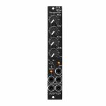
People also bought...
Doepfer A-118-2V Noise/Random/Sample & Hold Vintage Edition Module (black) (noise/random/sample & hold synth module)
Cat: 790467 Rel: 10 Nov 20
Signal generator module
Notes: Module A-118-2 generates the signals white noise, colored noise, continuous random voltage and stepped random voltage.
The noise signal is generated 100% analog by amplification of the noise of a transistor. White and colored noise are usually used as audio sources. The random voltages are normally used as control voltages (e.g. for filter frequency or any other voltage controlled parameter).
The A-118-2 gives you the ability to mix the relative amounts of Red and Blue noise (low/high frequency component) in the colored noise output.
For the continuous random voltage the rate of change (Rate) and amplitude (Level) of the random voltage can be adjusted. The continuous random voltage is used as source for the S&H/T&H unit. The type of operation can be set to S&H (sample and hold) or T&H (track and hold). When T&H is chosen the output signal follows the input signal as long as the Clock input is "high". As soon as the clock signal changes to "low" the last voltage is stored. When S&H is chosen the input signal is sampled at the rising edge of the Clock signal. For the Clock signal a "digital" signal (e.g. Clock, Gate, rectangle output of an LFO) is required. Dual color LEDs are used to indicates the continuous and stepped random voltages.
Controls:
Blue: share of the high frequencies in the the colored noise output
Red: share of the low frequencies in the the colored noise output
Rate: rate of change of the continuous random voltage
Level: amplitude of the continuous random voltage
TH/SH: switches between T&H und S&H
Inputs and outputs:
RND: continuous random voltage output (with LED display)
TH/SH: stepped random voltage output (with LED display)
Clk: Clock input of the S&H/T&H unit
C Noise: colored noise output
W Noise: white noise output
Important notes:
After power on it takes a few minutes until the two noise signals and the random signals are generated. The module is not faulty when after power on the signals do not appear immediately!
The S&H/T&H function is realized by pure analog circuitry (electronic switch followed by a holding capacitor and buffer). Consequently the output voltage drifts a bit in the holding state because the capacitor is discharged by parasitic resistors. The drift depends also upon environmental conditions like humidity or temperature.
The level of the random voltage changes with the settings of the Blue and Red controls. Especially the Red control affects the random voltage level (which is derived by low pass filtering from the colored noise signal) because the Red control changes the share of the low frequencies in the colored noise signal. The effect of the Blue control is much smaller because it changes the share of the high frequencies in the colored noise signal which are filtered out by the low pass of the random circuitry.
Power consumption: 20mA at +12V and 20mA at -12V
Depth: 40mm
HP : 4
… Read moreThe noise signal is generated 100% analog by amplification of the noise of a transistor. White and colored noise are usually used as audio sources. The random voltages are normally used as control voltages (e.g. for filter frequency or any other voltage controlled parameter).
The A-118-2 gives you the ability to mix the relative amounts of Red and Blue noise (low/high frequency component) in the colored noise output.
For the continuous random voltage the rate of change (Rate) and amplitude (Level) of the random voltage can be adjusted. The continuous random voltage is used as source for the S&H/T&H unit. The type of operation can be set to S&H (sample and hold) or T&H (track and hold). When T&H is chosen the output signal follows the input signal as long as the Clock input is "high". As soon as the clock signal changes to "low" the last voltage is stored. When S&H is chosen the input signal is sampled at the rising edge of the Clock signal. For the Clock signal a "digital" signal (e.g. Clock, Gate, rectangle output of an LFO) is required. Dual color LEDs are used to indicates the continuous and stepped random voltages.
Controls:
Blue: share of the high frequencies in the the colored noise output
Red: share of the low frequencies in the the colored noise output
Rate: rate of change of the continuous random voltage
Level: amplitude of the continuous random voltage
TH/SH: switches between T&H und S&H
Inputs and outputs:
RND: continuous random voltage output (with LED display)
TH/SH: stepped random voltage output (with LED display)
Clk: Clock input of the S&H/T&H unit
C Noise: colored noise output
W Noise: white noise output
Important notes:
After power on it takes a few minutes until the two noise signals and the random signals are generated. The module is not faulty when after power on the signals do not appear immediately!
The S&H/T&H function is realized by pure analog circuitry (electronic switch followed by a holding capacitor and buffer). Consequently the output voltage drifts a bit in the holding state because the capacitor is discharged by parasitic resistors. The drift depends also upon environmental conditions like humidity or temperature.
The level of the random voltage changes with the settings of the Blue and Red controls. Especially the Red control affects the random voltage level (which is derived by low pass filtering from the colored noise signal) because the Red control changes the share of the low frequencies in the colored noise signal. The effect of the Blue control is much smaller because it changes the share of the high frequencies in the colored noise signal which are filtered out by the low pass of the random circuitry.
Power consumption: 20mA at +12V and 20mA at -12V
Depth: 40mm
HP : 4
1 in stock $94.89
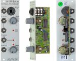
People also bought...
Doepfer A-119 External Input Envelope Follower Module (silver) (external/envelope follower/preamp/controller/comparator synth module)
Cat: 577771 Rel: 29 Nov 17
Envelope follower & pre-amplifier for microphone/line-signals - 8HP
Notes: Module A-119 (External Input / Envelope Follower) is designed to allow external audio signals to be integrated into the System A-100. It comprises a pre-amp, envelope follower, and comparator.
The pre-amp has two inputs: an unbalanced input for line level signals, with a gain factor of from 0 to 20, and a balanced input with a gain factor of from 0 to 500, for insertion of low level signals, for instance from a microphone or electric guitar.
The Envelope Follower reads the signal level of the input, and puts out a proportional voltage as an envelope at its own output.
The comparator generates a gate signal whenever the input goes above an adjustable trigger threshold.
Three LED's help you keep track of overload, the envelope, and the gate signal.
… Read moreThe pre-amp has two inputs: an unbalanced input for line level signals, with a gain factor of from 0 to 20, and a balanced input with a gain factor of from 0 to 500, for insertion of low level signals, for instance from a microphone or electric guitar.
The Envelope Follower reads the signal level of the input, and puts out a proportional voltage as an envelope at its own output.
The comparator generates a gate signal whenever the input goes above an adjustable trigger threshold.
Three LED's help you keep track of overload, the envelope, and the gate signal.
5 in stock $67.78
Click for better price!
or call +44 20 7424 1960
quote 577771
quote 577771
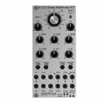
People also bought...
Doepfer A-121s Stereo Multimode Filter Module (silver) (dual/stereo/filter synth module)
Cat: 880248 Rel: 19 Aug 22
Module A-121s is a dual multimode filter which can be used for stereo applications as well as for parallel or serial organized dual mono filters.
Notes: Module A-121s is a dual multimode filter which can be used for stereo applications as well as for parallel or serial organized dual mono filters. The core is a 12dB multimode filter identical to the modules A-121-2 and A-121-3. The selection of the filter type is continuously from lowpass via notch and highpass to bandpass. We attached great importance to the usability of the manual controls and CV inputs for both stereo and dual mono applications. For the filter parameters frequency (F), resonance (Q) and type (T) common controls and CV inputs as well as single controls and CV inputs are available. For the filter frequency in addition a manual control and CV input for the filter spread (frequency difference or delta F) is available.
Controls:
F: master frequency control for both filters (large knob)
Type 1 / Type 2: filter type panning/morphing L-N-H-B
Link to 1: Toggle switch so that Type 1 also controls type of filter 2 (i.e. simultaneous filter type control for both filters)
SFM1 / SFM2: Single Frequency Modulation controls (polarizers), connected to the corresponding sockets SFM1/SFM2 (socket SFM1 is normalled to a fixed positive voltage, SFM2 is normalled to SFM1, that way the controls SFM1/SFM2 work as frequency controls for each filter provided that no modulation signals are patched to the SFM1/SFM2 sockets)
CFM: common frequency control, controls two VC-polarizers which process the signals connected to the two sockets CFM1/CFM2, CFM2 is normalled to CFM1, that way also the same modulation signal (e.g. an envelope generator) can be used for both filters and the level controlled simultaneously by the CFM control
Delta F: controls the difference between the frequencies of the two filters manually (frequency "spread"), at centre position the frequencies are the same
Delta FM: controls the level of the Delta FM signal (socket), which allows to control the spread between the frequencies also by an external control voltage (e.g. by an LFO or ADSR)
Q: controls the resonance of both filters simultaneously
Level 1 / Level 2: attenuators for the two audio inputs
QM/TM1, QM/TM2: attenuators for the modulation inputs QM/TM1 and QM/TM2
Sockets:
In1 / In2: audio inputs (In2 is normalled to In1)
Out1 / Out2: audio outputs
F: common frequency control input for both filters (~ 1V/oct)
Delta FM: Control voltage for frequency spread, processed by the polarizer Delta FM
SFM1 / SFM2: single frequency modulation inputs, processed by the polarizers SFM1 and SFM2, SFM1 is normalled to a fixed positive voltage, SFM2 is normalled to SFM1#
CFM1 / CFM2: common frequency modulation inputs, processed by the two voltage controlled polarizers controlled by CFM knob, CFM2 is normalled to CFM1
QM/TM1, QM/TM2: the addressing of these sockets/attenuators is defined by internal jumpers. QM means Q modulation (i.e. resonance modulation), TM means filter type modulation (QM1 = resonance modulation filter 1, QM2 = resonance modulation filter 2, TM1 = filter type modulation filter 1, TM2 = filter type modulation filter 2), socket QM/TM1 is normalled to a fixed positive voltage, QM/TM2 is normalled to QM/TM1
A 45 degrees triangle next to a socket means that the switching contact of the socket is normalled to a fixed positive voltage (SFM1, QM/TM1).
A vertical triangle indicates the normalling of two sockets (In1>In2, SFM1>SFM2, CFM1>CFM2, QM/TM1>QM/TM2).
If the filters do not behave as expected please pay attention to these peculiarities:
For the controls SFM1, SFM2, CFM, Delta F and Delta FM the centre position is the neutral position as these are polarizers. If the filter behaves unexpected these controls should be set to centre positions for the time being.
For the controls F, Q, Level 1, Level 2, QM/TM1 und QM/TM2 the fully CCW position is the neutral position as these are standard attenuators. If the filter behaves unexpected at least the controls QM/TM1 and QM/TM2 should be set to fully CCW. Via the normalling of the sockets QM/TM1 and QM/TM2 and the associated controls the filter parameters adjusted by the major controls (e.g. Type 1, Type 2 or Q) may be overwritten.
By means of small circles at the bottom right side of the front panel the user can mark the function of the QM/TM inputs. These assignments are possible:
QM/TM1 controls QM1, QM/TM2 controls QM2, the filter types are not controlled by external CVs
QM/TM1 controls TM1, QM/TM2 controls TM2, the resonances are not controlled by external CVs
QM/TM1 controls QM1 and QM2 simultaneously, QM/TM2 controls TM1 and TM2 simultaneously
Depth: 45mm
HP : 12
… Read moreControls:
F: master frequency control for both filters (large knob)
Type 1 / Type 2: filter type panning/morphing L-N-H-B
Link to 1: Toggle switch so that Type 1 also controls type of filter 2 (i.e. simultaneous filter type control for both filters)
SFM1 / SFM2: Single Frequency Modulation controls (polarizers), connected to the corresponding sockets SFM1/SFM2 (socket SFM1 is normalled to a fixed positive voltage, SFM2 is normalled to SFM1, that way the controls SFM1/SFM2 work as frequency controls for each filter provided that no modulation signals are patched to the SFM1/SFM2 sockets)
CFM: common frequency control, controls two VC-polarizers which process the signals connected to the two sockets CFM1/CFM2, CFM2 is normalled to CFM1, that way also the same modulation signal (e.g. an envelope generator) can be used for both filters and the level controlled simultaneously by the CFM control
Delta F: controls the difference between the frequencies of the two filters manually (frequency "spread"), at centre position the frequencies are the same
Delta FM: controls the level of the Delta FM signal (socket), which allows to control the spread between the frequencies also by an external control voltage (e.g. by an LFO or ADSR)
Q: controls the resonance of both filters simultaneously
Level 1 / Level 2: attenuators for the two audio inputs
QM/TM1, QM/TM2: attenuators for the modulation inputs QM/TM1 and QM/TM2
Sockets:
In1 / In2: audio inputs (In2 is normalled to In1)
Out1 / Out2: audio outputs
F: common frequency control input for both filters (~ 1V/oct)
Delta FM: Control voltage for frequency spread, processed by the polarizer Delta FM
SFM1 / SFM2: single frequency modulation inputs, processed by the polarizers SFM1 and SFM2, SFM1 is normalled to a fixed positive voltage, SFM2 is normalled to SFM1#
CFM1 / CFM2: common frequency modulation inputs, processed by the two voltage controlled polarizers controlled by CFM knob, CFM2 is normalled to CFM1
QM/TM1, QM/TM2: the addressing of these sockets/attenuators is defined by internal jumpers. QM means Q modulation (i.e. resonance modulation), TM means filter type modulation (QM1 = resonance modulation filter 1, QM2 = resonance modulation filter 2, TM1 = filter type modulation filter 1, TM2 = filter type modulation filter 2), socket QM/TM1 is normalled to a fixed positive voltage, QM/TM2 is normalled to QM/TM1
A 45 degrees triangle next to a socket means that the switching contact of the socket is normalled to a fixed positive voltage (SFM1, QM/TM1).
A vertical triangle indicates the normalling of two sockets (In1>In2, SFM1>SFM2, CFM1>CFM2, QM/TM1>QM/TM2).
If the filters do not behave as expected please pay attention to these peculiarities:
For the controls SFM1, SFM2, CFM, Delta F and Delta FM the centre position is the neutral position as these are polarizers. If the filter behaves unexpected these controls should be set to centre positions for the time being.
For the controls F, Q, Level 1, Level 2, QM/TM1 und QM/TM2 the fully CCW position is the neutral position as these are standard attenuators. If the filter behaves unexpected at least the controls QM/TM1 and QM/TM2 should be set to fully CCW. Via the normalling of the sockets QM/TM1 and QM/TM2 and the associated controls the filter parameters adjusted by the major controls (e.g. Type 1, Type 2 or Q) may be overwritten.
By means of small circles at the bottom right side of the front panel the user can mark the function of the QM/TM inputs. These assignments are possible:
QM/TM1 controls QM1, QM/TM2 controls QM2, the filter types are not controlled by external CVs
QM/TM1 controls TM1, QM/TM2 controls TM2, the resonances are not controlled by external CVs
QM/TM1 controls QM1 and QM2 simultaneously, QM/TM2 controls TM1 and TM2 simultaneously
Depth: 45mm
HP : 12
2 in stock $234.62
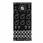
People also bought...
Doepfer A-121sV Stereo Multimode Filter Vintage Edition Module (black) (dual/stereo/filter synth module)
Cat: 880251 Rel: 18 Aug 22
Module A-121s is a dual multimode filter which can be used for stereo applications as well as for parallel or serial organized dual mono filters.
Notes: Module A-121s is a dual multimode filter which can be used for stereo applications as well as for parallel or serial organized dual mono filters. The core is a 12dB multimode filter identical to the modules A-121-2 and A-121-3. The selection of the filter type is continuously from lowpass via notch and highpass to bandpass. We attached great importance to the usability of the manual controls and CV inputs for both stereo and dual mono applications. For the filter parameters frequency (F), resonance (Q) and type (T) common controls and CV inputs as well as single controls and CV inputs are available. For the filter frequency in addition a manual control and CV input for the filter spread (frequency difference or delta F) is available.
Controls:
F: master frequency control for both filters (large knob)
Type 1 / Type 2: filter type panning/morphing L-N-H-B
Link to 1: Toggle switch so that Type 1 also controls type of filter 2 (i.e. simultaneous filter type control for both filters)
SFM1 / SFM2: Single Frequency Modulation controls (polarizers), connected to the corresponding sockets SFM1/SFM2 (socket SFM1 is normalled to a fixed positive voltage, SFM2 is normalled to SFM1, that way the controls SFM1/SFM2 work as frequency controls for each filter provided that no modulation signals are patched to the SFM1/SFM2 sockets)
CFM: common frequency control, controls two VC-polarizers which process the signals connected to the two sockets CFM1/CFM2, CFM2 is normalled to CFM1, that way also the same modulation signal (e.g. an envelope generator) can be used for both filters and the level controlled simultaneously by the CFM control
Delta F: controls the difference between the frequencies of the two filters manually (frequency "spread"), at centre position the frequencies are the same
Delta FM: controls the level of the Delta FM signal (socket), which allows to control the spread between the frequencies also by an external control voltage (e.g. by an LFO or ADSR)
Q: controls the resonance of both filters simultaneously
Level 1 / Level 2: attenuators for the two audio inputs
QM/TM1, QM/TM2: attenuators for the modulation inputs QM/TM1 and QM/TM2
Sockets:
In1 / In2: audio inputs (In2 is normalled to In1)
Out1 / Out2: audio outputs
F: common frequency control input for both filters (~ 1V/oct)
Delta FM: Control voltage for frequency spread, processed by the polarizer Delta FM
SFM1 / SFM2: single frequency modulation inputs, processed by the polarizers SFM1 and SFM2, SFM1 is normalled to a fixed positive voltage, SFM2 is normalled to SFM1#
CFM1 / CFM2: common frequency modulation inputs, processed by the two voltage controlled polarizers controlled by CFM knob, CFM2 is normalled to CFM1
QM/TM1, QM/TM2: the addressing of these sockets/attenuators is defined by internal jumpers. QM means Q modulation (i.e. resonance modulation), TM means filter type modulation (QM1 = resonance modulation filter 1, QM2 = resonance modulation filter 2, TM1 = filter type modulation filter 1, TM2 = filter type modulation filter 2), socket QM/TM1 is normalled to a fixed positive voltage, QM/TM2 is normalled to QM/TM1
A 45 degrees triangle next to a socket means that the switching contact of the socket is normalled to a fixed positive voltage (SFM1, QM/TM1).
A vertical triangle indicates the normalling of two sockets (In1>In2, SFM1>SFM2, CFM1>CFM2, QM/TM1>QM/TM2).
If the filters do not behave as expected please pay attention to these peculiarities:
For the controls SFM1, SFM2, CFM, Delta F and Delta FM the centre position is the neutral position as these are polarizers. If the filter behaves unexpected these controls should be set to centre positions for the time being.
For the controls F, Q, Level 1, Level 2, QM/TM1 und QM/TM2 the fully CCW position is the neutral position as these are standard attenuators. If the filter behaves unexpected at least the controls QM/TM1 and QM/TM2 should be set to fully CCW. Via the normalling of the sockets QM/TM1 and QM/TM2 and the associated controls the filter parameters adjusted by the major controls (e.g. Type 1, Type 2 or Q) may be overwritten.
By means of small circles at the bottom right side of the front panel the user can mark the function of the QM/TM inputs. These assignments are possible:
QM/TM1 controls QM1, QM/TM2 controls QM2, the filter types are not controlled by external CVs
QM/TM1 controls TM1, QM/TM2 controls TM2, the resonances are not controlled by external CVs
QM/TM1 controls QM1 and QM2 simultaneously, QM/TM2 controls TM1 and TM2 simultaneously
… Read moreControls:
F: master frequency control for both filters (large knob)
Type 1 / Type 2: filter type panning/morphing L-N-H-B
Link to 1: Toggle switch so that Type 1 also controls type of filter 2 (i.e. simultaneous filter type control for both filters)
SFM1 / SFM2: Single Frequency Modulation controls (polarizers), connected to the corresponding sockets SFM1/SFM2 (socket SFM1 is normalled to a fixed positive voltage, SFM2 is normalled to SFM1, that way the controls SFM1/SFM2 work as frequency controls for each filter provided that no modulation signals are patched to the SFM1/SFM2 sockets)
CFM: common frequency control, controls two VC-polarizers which process the signals connected to the two sockets CFM1/CFM2, CFM2 is normalled to CFM1, that way also the same modulation signal (e.g. an envelope generator) can be used for both filters and the level controlled simultaneously by the CFM control
Delta F: controls the difference between the frequencies of the two filters manually (frequency "spread"), at centre position the frequencies are the same
Delta FM: controls the level of the Delta FM signal (socket), which allows to control the spread between the frequencies also by an external control voltage (e.g. by an LFO or ADSR)
Q: controls the resonance of both filters simultaneously
Level 1 / Level 2: attenuators for the two audio inputs
QM/TM1, QM/TM2: attenuators for the modulation inputs QM/TM1 and QM/TM2
Sockets:
In1 / In2: audio inputs (In2 is normalled to In1)
Out1 / Out2: audio outputs
F: common frequency control input for both filters (~ 1V/oct)
Delta FM: Control voltage for frequency spread, processed by the polarizer Delta FM
SFM1 / SFM2: single frequency modulation inputs, processed by the polarizers SFM1 and SFM2, SFM1 is normalled to a fixed positive voltage, SFM2 is normalled to SFM1#
CFM1 / CFM2: common frequency modulation inputs, processed by the two voltage controlled polarizers controlled by CFM knob, CFM2 is normalled to CFM1
QM/TM1, QM/TM2: the addressing of these sockets/attenuators is defined by internal jumpers. QM means Q modulation (i.e. resonance modulation), TM means filter type modulation (QM1 = resonance modulation filter 1, QM2 = resonance modulation filter 2, TM1 = filter type modulation filter 1, TM2 = filter type modulation filter 2), socket QM/TM1 is normalled to a fixed positive voltage, QM/TM2 is normalled to QM/TM1
A 45 degrees triangle next to a socket means that the switching contact of the socket is normalled to a fixed positive voltage (SFM1, QM/TM1).
A vertical triangle indicates the normalling of two sockets (In1>In2, SFM1>SFM2, CFM1>CFM2, QM/TM1>QM/TM2).
If the filters do not behave as expected please pay attention to these peculiarities:
For the controls SFM1, SFM2, CFM, Delta F and Delta FM the centre position is the neutral position as these are polarizers. If the filter behaves unexpected these controls should be set to centre positions for the time being.
For the controls F, Q, Level 1, Level 2, QM/TM1 und QM/TM2 the fully CCW position is the neutral position as these are standard attenuators. If the filter behaves unexpected at least the controls QM/TM1 and QM/TM2 should be set to fully CCW. Via the normalling of the sockets QM/TM1 and QM/TM2 and the associated controls the filter parameters adjusted by the major controls (e.g. Type 1, Type 2 or Q) may be overwritten.
By means of small circles at the bottom right side of the front panel the user can mark the function of the QM/TM inputs. These assignments are possible:
QM/TM1 controls QM1, QM/TM2 controls QM2, the filter types are not controlled by external CVs
QM/TM1 controls TM1, QM/TM2 controls TM2, the resonances are not controlled by external CVs
QM/TM1 controls QM1 and QM2 simultaneously, QM/TM2 controls TM1 and TM2 simultaneously
1 in stock $242.97
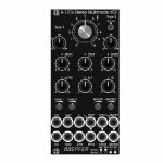
People also bought...
Doepfer A-121sV Stereo Multimode Filter Vintage Edition Module (black) (B-STOCK) (dual/stereo/filter synth module)
Cat: 924238 Rel: 01 Jan 90
B-STOCK: Box opened, but product is in excellent condition and in perfect working order
Notes: ***B-STOCK: Box opened, but product is in excellent condition and in perfect working order***
Module A-121s is a dual multimode filter which can be used for stereo applications as well as for parallel or serial organized dual mono filters. The core is a 12dB multimode filter identical to the modules A-121-2 and A-121-3. The selection of the filter type is continuously from lowpass via notch and highpass to bandpass. We attached great importance to the usability of the manual controls and CV inputs for both stereo and dual mono applications. For the filter parameters frequency (F), resonance (Q) and type (T) common controls and CV inputs as well as single controls and CV inputs are available. For the filter frequency in addition a manual control and CV input for the filter spread (frequency difference or delta F) is available.
Controls:
F: master frequency control for both filters (large knob)
Type 1 / Type 2: filter type panning/morphing L-N-H-B
Link to 1: Toggle switch so that Type 1 also controls type of filter 2 (i.e. simultaneous filter type control for both filters)
SFM1 / SFM2: Single Frequency Modulation controls (polarizers), connected to the corresponding sockets SFM1/SFM2 (socket SFM1 is normalled to a fixed positive voltage, SFM2 is normalled to SFM1, that way the controls SFM1/SFM2 work as frequency controls for each filter provided that no modulation signals are patched to the SFM1/SFM2 sockets)
CFM: common frequency control, controls two VC-polarizers which process the signals connected to the two sockets CFM1/CFM2, CFM2 is normalled to CFM1, that way also the same modulation signal (e.g. an envelope generator) can be used for both filters and the level controlled simultaneously by the CFM control
Delta F: controls the difference between the frequencies of the two filters manually (frequency "spread"), at centre position the frequencies are the same
Delta FM: controls the level of the Delta FM signal (socket), which allows to control the spread between the frequencies also by an external control voltage (e.g. by an LFO or ADSR)
Q: controls the resonance of both filters simultaneously
Level 1 / Level 2: attenuators for the two audio inputs
QM/TM1, QM/TM2: attenuators for the modulation inputs QM/TM1 and QM/TM2
Sockets:
In1 / In2: audio inputs (In2 is normalled to In1)
Out1 / Out2: audio outputs
F: common frequency control input for both filters (~ 1V/oct)
Delta FM: Control voltage for frequency spread, processed by the polarizer Delta FM
SFM1 / SFM2: single frequency modulation inputs, processed by the polarizers SFM1 and SFM2, SFM1 is normalled to a fixed positive voltage, SFM2 is normalled to SFM1#
CFM1 / CFM2: common frequency modulation inputs, processed by the two voltage controlled polarizers controlled by CFM knob, CFM2 is normalled to CFM1
QM/TM1, QM/TM2: the addressing of these sockets/attenuators is defined by internal jumpers. QM means Q modulation (i.e. resonance modulation), TM means filter type modulation (QM1 = resonance modulation filter 1, QM2 = resonance modulation filter 2, TM1 = filter type modulation filter 1, TM2 = filter type modulation filter 2), socket QM/TM1 is normalled to a fixed positive voltage, QM/TM2 is normalled to QM/TM1
A 45 degrees triangle next to a socket means that the switching contact of the socket is normalled to a fixed positive voltage (SFM1, QM/TM1).
A vertical triangle indicates the normalling of two sockets (In1>In2, SFM1>SFM2, CFM1>CFM2, QM/TM1>QM/TM2).
If the filters do not behave as expected please pay attention to these peculiarities:
For the controls SFM1, SFM2, CFM, Delta F and Delta FM the centre position is the neutral position as these are polarizers. If the filter behaves unexpected these controls should be set to centre positions for the time being.
For the controls F, Q, Level 1, Level 2, QM/TM1 und QM/TM2 the fully CCW position is the neutral position as these are standard attenuators. If the filter behaves unexpected at least the controls QM/TM1 and QM/TM2 should be set to fully CCW. Via the normalling of the sockets QM/TM1 and QM/TM2 and the associated controls the filter parameters adjusted by the major controls (e.g. Type 1, Type 2 or Q) may be overwritten.
By means of small circles at the bottom right side of the front panel the user can mark the function of the QM/TM inputs. These assignments are possible:
QM/TM1 controls QM1, QM/TM2 controls QM2, the filter types are not controlled by external CVs
QM/TM1 controls TM1, QM/TM2 controls TM2, the resonances are not controlled by external CVs
QM/TM1 controls QM1 and QM2 simultaneously, QM/TM2 controls TM1 and TM2 simultaneously
… Read moreModule A-121s is a dual multimode filter which can be used for stereo applications as well as for parallel or serial organized dual mono filters. The core is a 12dB multimode filter identical to the modules A-121-2 and A-121-3. The selection of the filter type is continuously from lowpass via notch and highpass to bandpass. We attached great importance to the usability of the manual controls and CV inputs for both stereo and dual mono applications. For the filter parameters frequency (F), resonance (Q) and type (T) common controls and CV inputs as well as single controls and CV inputs are available. For the filter frequency in addition a manual control and CV input for the filter spread (frequency difference or delta F) is available.
Controls:
F: master frequency control for both filters (large knob)
Type 1 / Type 2: filter type panning/morphing L-N-H-B
Link to 1: Toggle switch so that Type 1 also controls type of filter 2 (i.e. simultaneous filter type control for both filters)
SFM1 / SFM2: Single Frequency Modulation controls (polarizers), connected to the corresponding sockets SFM1/SFM2 (socket SFM1 is normalled to a fixed positive voltage, SFM2 is normalled to SFM1, that way the controls SFM1/SFM2 work as frequency controls for each filter provided that no modulation signals are patched to the SFM1/SFM2 sockets)
CFM: common frequency control, controls two VC-polarizers which process the signals connected to the two sockets CFM1/CFM2, CFM2 is normalled to CFM1, that way also the same modulation signal (e.g. an envelope generator) can be used for both filters and the level controlled simultaneously by the CFM control
Delta F: controls the difference between the frequencies of the two filters manually (frequency "spread"), at centre position the frequencies are the same
Delta FM: controls the level of the Delta FM signal (socket), which allows to control the spread between the frequencies also by an external control voltage (e.g. by an LFO or ADSR)
Q: controls the resonance of both filters simultaneously
Level 1 / Level 2: attenuators for the two audio inputs
QM/TM1, QM/TM2: attenuators for the modulation inputs QM/TM1 and QM/TM2
Sockets:
In1 / In2: audio inputs (In2 is normalled to In1)
Out1 / Out2: audio outputs
F: common frequency control input for both filters (~ 1V/oct)
Delta FM: Control voltage for frequency spread, processed by the polarizer Delta FM
SFM1 / SFM2: single frequency modulation inputs, processed by the polarizers SFM1 and SFM2, SFM1 is normalled to a fixed positive voltage, SFM2 is normalled to SFM1#
CFM1 / CFM2: common frequency modulation inputs, processed by the two voltage controlled polarizers controlled by CFM knob, CFM2 is normalled to CFM1
QM/TM1, QM/TM2: the addressing of these sockets/attenuators is defined by internal jumpers. QM means Q modulation (i.e. resonance modulation), TM means filter type modulation (QM1 = resonance modulation filter 1, QM2 = resonance modulation filter 2, TM1 = filter type modulation filter 1, TM2 = filter type modulation filter 2), socket QM/TM1 is normalled to a fixed positive voltage, QM/TM2 is normalled to QM/TM1
A 45 degrees triangle next to a socket means that the switching contact of the socket is normalled to a fixed positive voltage (SFM1, QM/TM1).
A vertical triangle indicates the normalling of two sockets (In1>In2, SFM1>SFM2, CFM1>CFM2, QM/TM1>QM/TM2).
If the filters do not behave as expected please pay attention to these peculiarities:
For the controls SFM1, SFM2, CFM, Delta F and Delta FM the centre position is the neutral position as these are polarizers. If the filter behaves unexpected these controls should be set to centre positions for the time being.
For the controls F, Q, Level 1, Level 2, QM/TM1 und QM/TM2 the fully CCW position is the neutral position as these are standard attenuators. If the filter behaves unexpected at least the controls QM/TM1 and QM/TM2 should be set to fully CCW. Via the normalling of the sockets QM/TM1 and QM/TM2 and the associated controls the filter parameters adjusted by the major controls (e.g. Type 1, Type 2 or Q) may be overwritten.
By means of small circles at the bottom right side of the front panel the user can mark the function of the QM/TM inputs. These assignments are possible:
QM/TM1 controls QM1, QM/TM2 controls QM2, the filter types are not controlled by external CVs
QM/TM1 controls TM1, QM/TM2 controls TM2, the resonances are not controlled by external CVs
QM/TM1 controls QM1 and QM2 simultaneously, QM/TM2 controls TM1 and TM2 simultaneously
1 in stock $218.27
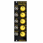
People also bought...
Doepfer A-124 VCF5 Wasp Filter 12dB Multimode Filter Module (special edition, black/yellow) (filter synth module)
Cat: 671564 Rel: 29 Nov 17
12dB multi-mode filter with unique classic circuitry, based on the filter from the 70s EDP Wasp synth
Notes: Module A-124 is a special 12dB multimode filter using the "strange" filter circuit of the "EDP Wasp" (an analog synthesizer with black/yellow case built end of the seventies, manufactured by the UK company "Electronic Dream Plant" with Chris Huggett und Adrian Wagner). This design "abuses" digital inverters as analog operational amplifiers leading to distortions and other "dirty" effects that generate the specific sound of this filter. The filter is equipped with a band pass output and a combined low/notch/high pass output. For this output a control knob defines the relation between low and high pass signal. If both signals appear at the same level (i.e. middle position of the Mix knob) one obtains a notch filter. Otherwise the low or high pass signal predominates. The module does not feature self-oscillation in contrast to most of the other filters of the A-100 system.
Inputs: Audio In, CV In (2x)
Outputs: Bandpass Out, Low/Highpass Mix-Out
Controls: Audio and CV attenuator, Frequency, Resonance, LP/HP Mix
The function and operation of this module is very similar to the module SEM VCF A-106-5. But the sound of both filters is very different! The only functional difference is the position of the sockets and controls, and the function of the controls CV2 (A-124: normal attenuator, A-106-5: polarizer).
- 3U Eurorack module, 8HP wide, 45mm deep
- Current draw 30mA
… Read moreInputs: Audio In, CV In (2x)
Outputs: Bandpass Out, Low/Highpass Mix-Out
Controls: Audio and CV attenuator, Frequency, Resonance, LP/HP Mix
The function and operation of this module is very similar to the module SEM VCF A-106-5. But the sound of both filters is very different! The only functional difference is the position of the sockets and controls, and the function of the controls CV2 (A-124: normal attenuator, A-106-5: polarizer).
- 3U Eurorack module, 8HP wide, 45mm deep
- Current draw 30mA
8 in stock $79.25
Click for better price!
or call +44 20 7424 1960
quote 671564
quote 671564
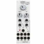
People also bought...
Doepfer A-126-2 Frequency Shifter Eurorack Module (eurorack oscillator/phase shifter/pitch shifter/VCA module)
Cat: 847081 Rel: 17 Nov 21
Voltage Controlled Frequency Shifter II
Notes: Module A-126-2 is a fully analog frequency shifter for audio signals. A frequency shifter is an audio processing unit that shifts each frequency of the incoming audio signal by the same frequency. If the shifting frequency is e.g. 200Hz an incoming audio frequency of 1000 Hz becomes 1200 Hz, 2000Hz becomes 2200 Hz, 3000 Hz becomes 3200 Hz and so on. Pay attention that this is different from pitch shifting where all frequencies are shifted proportional (e.g. 1000>1200Hz, 2000>2400Hz, 3000>3600Hz) !
The frequency range of the internal quadrature VCO is about 8 octaves (about 20Hz ... 5kHz). If required an external quadrature VCO can be used.
The module is equipped with these controls, inputs and outputs:
Frequ. 1: first manual control of the shifting frequency (factory setting: coarse, range about 20Hz - 5 kHz)
Frequ. 2: second manual control of the shifting frequency (factory setting: fine)
by means of internal jumpers the sensitivity of Frequ.1 and 2 can be swapped (i.e. Frequ.1 = fine and Frequ.2 = coarse)
the relation between coarse and fine control is about 25:1 (corresponding to about 8 octaves to 1/3 octave)
FCV In (socket) and FCV (small control without knob): control voltage input with attenuator for the external voltage control of the shifting frequency
Mix: manual control of the up/down shift panning unit, fully CCW = down shift, fully CW = up shift, in between a mixture of down and up
Mix CV In (socket) and Mix CV (small control without knob): control voltage input with attenuator for the mixing unit for external voltage control of the up/down mixing
Audio In (socket), Level (small control without knob) and Overload (LED): audio input with attenuator, typ. audio in level = 1Vpp, the level control has to be adjusted so that the overload LED just begins to light up a bit, when the LED is fully on clipping/distortion occurs, when the LED is permanently off the input level is too low and the signal-to-noise ratio increases
Audio Out (socket): audio output of the frequency shifter
Squelch (small control without knob): controls the squelch function: fully CCW (Env.) the output VCA is controlled by the envelope signal, which is derived from the audio input signal, fully CW (open) the output VCA is permanently open (no squelch function), in between the squelch intensity can be adjusted
Quadrature VCO Outputs (sockets Sin and Cos): outputs of the internal quadrature oscillator, about 12Vpp level (+6V/-6V)
Ext. Inputs Sin and Cos (sockets): required when an external quadrature VCO (e.g. A-143-9 with a wider frequency range or A-110-4 with thru zero feature or A-110-6 with different waveforms) is used instead of the internal quadrature VCO, the levels of the external VCO should be about 10Vpp (8...10Vpp are OK) and the signals have to be symmetrical around zero Volts, the sockets are normalled to the internal quadrature VCO (i.e. the sockets are equipped with switching contacts that interrupt the internal connection as soon as a plug inserted)
VCA ext. CV (socket): used when an external control voltage (e.g. from an envelope generator) should be used to control the output VCA instead of the internal squelch unit, the socket is normalled to the output of the squelch control (i.e. the socket is equipped with a switching contact that interrupts the internal squelch connection as soon as a plug inserted). From about +8V external control voltage the VCA is fully open.
Internal terminals (pin headers, e.g. for a DIY breakout module):
envelope follower output
dome filter output 1
dome filter output 2
ring modulator 1 output
ring modulator 2 output
Up shift output
Down shift output
… Read moreThe frequency range of the internal quadrature VCO is about 8 octaves (about 20Hz ... 5kHz). If required an external quadrature VCO can be used.
The module is equipped with these controls, inputs and outputs:
Frequ. 1: first manual control of the shifting frequency (factory setting: coarse, range about 20Hz - 5 kHz)
Frequ. 2: second manual control of the shifting frequency (factory setting: fine)
by means of internal jumpers the sensitivity of Frequ.1 and 2 can be swapped (i.e. Frequ.1 = fine and Frequ.2 = coarse)
the relation between coarse and fine control is about 25:1 (corresponding to about 8 octaves to 1/3 octave)
FCV In (socket) and FCV (small control without knob): control voltage input with attenuator for the external voltage control of the shifting frequency
Mix: manual control of the up/down shift panning unit, fully CCW = down shift, fully CW = up shift, in between a mixture of down and up
Mix CV In (socket) and Mix CV (small control without knob): control voltage input with attenuator for the mixing unit for external voltage control of the up/down mixing
Audio In (socket), Level (small control without knob) and Overload (LED): audio input with attenuator, typ. audio in level = 1Vpp, the level control has to be adjusted so that the overload LED just begins to light up a bit, when the LED is fully on clipping/distortion occurs, when the LED is permanently off the input level is too low and the signal-to-noise ratio increases
Audio Out (socket): audio output of the frequency shifter
Squelch (small control without knob): controls the squelch function: fully CCW (Env.) the output VCA is controlled by the envelope signal, which is derived from the audio input signal, fully CW (open) the output VCA is permanently open (no squelch function), in between the squelch intensity can be adjusted
Quadrature VCO Outputs (sockets Sin and Cos): outputs of the internal quadrature oscillator, about 12Vpp level (+6V/-6V)
Ext. Inputs Sin and Cos (sockets): required when an external quadrature VCO (e.g. A-143-9 with a wider frequency range or A-110-4 with thru zero feature or A-110-6 with different waveforms) is used instead of the internal quadrature VCO, the levels of the external VCO should be about 10Vpp (8...10Vpp are OK) and the signals have to be symmetrical around zero Volts, the sockets are normalled to the internal quadrature VCO (i.e. the sockets are equipped with switching contacts that interrupt the internal connection as soon as a plug inserted)
VCA ext. CV (socket): used when an external control voltage (e.g. from an envelope generator) should be used to control the output VCA instead of the internal squelch unit, the socket is normalled to the output of the squelch control (i.e. the socket is equipped with a switching contact that interrupts the internal squelch connection as soon as a plug inserted). From about +8V external control voltage the VCA is fully open.
Internal terminals (pin headers, e.g. for a DIY breakout module):
envelope follower output
dome filter output 1
dome filter output 2
ring modulator 1 output
ring modulator 2 output
Up shift output
Down shift output
1 in stock $324.31
Click for better price!
or call +44 20 7424 1960
quote 847081
quote 847081
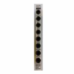
People also bought...
Doepfer A-126-2exp Voltage Controlled Frequency Shifter II - Expansion Module (silver) (expander synth module)
Cat: 852803 Rel: 04 Feb 22
An expander for the A-126-2 Voltage Controlled Frequency Shifter.
Notes: The Doepfer A-126-2exp is an expander for the A-126-2 Voltage Controlled Frequency Shifter.
It adds two outputs from the Dome filter (+45 and -45 degrees) as well as separate outputs from the ring modulators 1 and 2, and from the internal envelope generator. Furthermore, it offers dedicated outputs for Up and Down Shift, allowing the module to be patched in stereo.
*Note: The expander can only be used in conjunction with the module A-126-2.
HP : 2
… Read moreIt adds two outputs from the Dome filter (+45 and -45 degrees) as well as separate outputs from the ring modulators 1 and 2, and from the internal envelope generator. Furthermore, it offers dedicated outputs for Up and Down Shift, allowing the module to be patched in stereo.
*Note: The expander can only be used in conjunction with the module A-126-2.
HP : 2
1 in stock $49.79
Click for better price!
or call +44 20 7424 1960
quote 852803
quote 852803
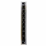
People also bought...
Doepfer A-126-2exp Voltage Controlled Frequency Shifter II - Expansion Vintage Edition Module (black) (expander synth module)
Cat: 852807 Rel: 04 Feb 22
An expander for the A-126-2 Voltage Controlled Frequency Shifter.
Notes: The Doepfer A-126-2exp is an expander for the A-126-2 Voltage Controlled Frequency Shifter.
It adds two outputs from the Dome filter (+45 and -45 degrees) as well as separate outputs from the ring modulators 1 and 2, and from the internal envelope generator. Furthermore, it offers dedicated outputs for Up and Down Shift, allowing the module to be patched in stereo.
*Note: The expander can only be used in conjunction with the module A-126-2.
HP : 2
… Read moreIt adds two outputs from the Dome filter (+45 and -45 degrees) as well as separate outputs from the ring modulators 1 and 2, and from the internal envelope generator. Furthermore, it offers dedicated outputs for Up and Down Shift, allowing the module to be patched in stereo.
*Note: The expander can only be used in conjunction with the module A-126-2.
HP : 2
2 in stock $52.13
Click for better price!
or call +44 20 7424 1960
quote 852807
quote 852807
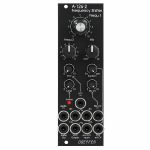
People also bought...
Doepfer A-126-2v Frequency Shifter Vintage Edition Module (black) (oscillator/phase shifter/pitch shifter/VCA synth module)
Cat: 847083 Rel: 17 Nov 21
Voltage Controlled Frequency Shifter II
Notes: 'Vintage' black panel version of Doepfer's updated frequency shifter module, offering weird and wonderful effects by shifting all frequencies by a fixed amount. Unique sound, not to be confused with pitch shifting.
Supplier's Notes:
Module A-126-2 is a fully analog frequency shifter for audio signals. A frequency shifter is an audio processing unit that shifts each frequency of the incoming audio signal by the same frequency. If the shifting frequency is e.g. 200Hz an incoming audio frequency of 1000 Hz becomes 1200 Hz, 2000Hz becomes 2200 Hz, 3000 Hz becomes 3200 Hz and so on. Pay attention that this is different from pitch shifting where all frequencies are shifted proportional (e.g. 1000>1200Hz, 2000>2400Hz, 3000>3600Hz) !
The frequency range of the internal quadrature VCO is about 8 octaves (about 20Hz ... 5kHz). If required an external quadrature VCO can be used.
The module is equipped with these controls, inputs and outputs:
Frequ. 1: first manual control of the shifting frequency (factory setting: coarse, range about 20Hz - 5 kHz)
Frequ. 2: second manual control of the shifting frequency (factory setting: fine)
by means of internal jumpers the sensitivity of Frequ.1 and 2 can be swapped (i.e. Frequ.1 = fine and Frequ.2 = coarse)
the relation between coarse and fine control is about 25:1 (corresponding to about 8 octaves to 1/3 octave)
FCV In (socket) and FCV (small control without knob): control voltage input with attenuator for the external voltage control of the shifting frequency
Mix: manual control of the up/down shift panning unit, fully CCW = down shift, fully CW = up shift, in between a mixture of down and up
Mix CV In (socket) and Mix CV (small control without knob): control voltage input with attenuator for the mixing unit for external voltage control of the up/down mixing
Audio In (socket), Level (small control without knob) and Overload (LED): audio input with attenuator, typ. audio in level = 1Vpp, the level control has to be adjusted so that the overload LED just begins to light up a bit, when the LED is fully on clipping/distortion occurs, when the LED is permanently off the input level is too low and the signal-to-noise ratio increases
Audio Out (socket): audio output of the frequency shifter
Squelch (small control without knob): controls the squelch function: fully CCW (Env.) the output VCA is controlled by the envelope signal, which is derived from the audio input signal, fully CW (open) the output VCA is permanently open (no squelch function), in between the squelch intensity can be adjusted
Quadrature VCO Outputs (sockets Sin and Cos): outputs of the internal quadrature oscillator, about 12Vpp level (+6V/-6V)
Ext. Inputs Sin and Cos (sockets): required when an external quadrature VCO (e.g. A-143-9 with a wider frequency range or A-110-4 with thru zero feature or A-110-6 with different waveforms) is used instead of the internal quadrature VCO, the levels of the external VCO should be about 10Vpp (8...10Vpp are OK) and the signals have to be symmetrical around zero Volts, the sockets are normalled to the internal quadrature VCO (i.e. the sockets are equipped with switching contacts that interrupt the internal connection as soon as a plug inserted)
VCA ext. CV (socket): used when an external control voltage (e.g. from an envelope generator) should be used to control the output VCA instead of the internal squelch unit, the socket is normalled to the output of the squelch control (i.e. the socket is equipped with a switching contact that interrupts the internal squelch connection as soon as a plug inserted). From about +8V external control voltage the VCA is fully open.
Internal terminals (pin headers, e.g. for a DIY breakout module):
envelope follower output
dome filter output 1
dome filter output 2
ring modulator 1 output
ring modulator 2 output
Up shift output
Down shift output
… Read moreSupplier's Notes:
Module A-126-2 is a fully analog frequency shifter for audio signals. A frequency shifter is an audio processing unit that shifts each frequency of the incoming audio signal by the same frequency. If the shifting frequency is e.g. 200Hz an incoming audio frequency of 1000 Hz becomes 1200 Hz, 2000Hz becomes 2200 Hz, 3000 Hz becomes 3200 Hz and so on. Pay attention that this is different from pitch shifting where all frequencies are shifted proportional (e.g. 1000>1200Hz, 2000>2400Hz, 3000>3600Hz) !
The frequency range of the internal quadrature VCO is about 8 octaves (about 20Hz ... 5kHz). If required an external quadrature VCO can be used.
The module is equipped with these controls, inputs and outputs:
Frequ. 1: first manual control of the shifting frequency (factory setting: coarse, range about 20Hz - 5 kHz)
Frequ. 2: second manual control of the shifting frequency (factory setting: fine)
by means of internal jumpers the sensitivity of Frequ.1 and 2 can be swapped (i.e. Frequ.1 = fine and Frequ.2 = coarse)
the relation between coarse and fine control is about 25:1 (corresponding to about 8 octaves to 1/3 octave)
FCV In (socket) and FCV (small control without knob): control voltage input with attenuator for the external voltage control of the shifting frequency
Mix: manual control of the up/down shift panning unit, fully CCW = down shift, fully CW = up shift, in between a mixture of down and up
Mix CV In (socket) and Mix CV (small control without knob): control voltage input with attenuator for the mixing unit for external voltage control of the up/down mixing
Audio In (socket), Level (small control without knob) and Overload (LED): audio input with attenuator, typ. audio in level = 1Vpp, the level control has to be adjusted so that the overload LED just begins to light up a bit, when the LED is fully on clipping/distortion occurs, when the LED is permanently off the input level is too low and the signal-to-noise ratio increases
Audio Out (socket): audio output of the frequency shifter
Squelch (small control without knob): controls the squelch function: fully CCW (Env.) the output VCA is controlled by the envelope signal, which is derived from the audio input signal, fully CW (open) the output VCA is permanently open (no squelch function), in between the squelch intensity can be adjusted
Quadrature VCO Outputs (sockets Sin and Cos): outputs of the internal quadrature oscillator, about 12Vpp level (+6V/-6V)
Ext. Inputs Sin and Cos (sockets): required when an external quadrature VCO (e.g. A-143-9 with a wider frequency range or A-110-4 with thru zero feature or A-110-6 with different waveforms) is used instead of the internal quadrature VCO, the levels of the external VCO should be about 10Vpp (8...10Vpp are OK) and the signals have to be symmetrical around zero Volts, the sockets are normalled to the internal quadrature VCO (i.e. the sockets are equipped with switching contacts that interrupt the internal connection as soon as a plug inserted)
VCA ext. CV (socket): used when an external control voltage (e.g. from an envelope generator) should be used to control the output VCA instead of the internal squelch unit, the socket is normalled to the output of the squelch control (i.e. the socket is equipped with a switching contact that interrupts the internal squelch connection as soon as a plug inserted). From about +8V external control voltage the VCA is fully open.
Internal terminals (pin headers, e.g. for a DIY breakout module):
envelope follower output
dome filter output 1
dome filter output 2
ring modulator 1 output
ring modulator 2 output
Up shift output
Down shift output
2 in stock $326.20
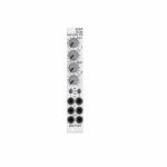
People also bought...
Doepfer A-130-2 Dual Linear/Exponential VCA Slim Line Series Module (dual/stereo/VCA synth module)
Cat: 731940 Rel: 11 Jun 19
Compact two-channel VCA - 4HP
Notes: Module A-130-2 is the slim version of module A-132-3 and offers essentially the same features. But the distances between the controls are smaller and rubberized small-sized knobs are used. In return the front panel has 4 HP only which is half the width of the A-132-3. The module is primarily planned for applications where only limited space is available.
The module is composed of two identical voltage controlled amplifiers (VCA). Each VCA has a manual gain control (also named Initial Gain) and a control voltage input with attenuator. The character of the control scale can be switched to linear or exponential. All inputs and outputs are DC coupled. Consequently the VCAs can be used to process both audio and control voltages (e.g. for voltage control of the level of LFO or envelope signals). The signal input has no attenuator available but is capable to process up to 16Vpp signals (i.e. -8V...+8V) without distortion. For the processing of higher levels an external attenuator (e.g. A-183-1) is recommended.
The amplification range is 0...1. Even with a higher external control voltage the amplification remains at 1 (kind of "amplification clipping" at 1).
Controls (for each of both units):
- Gain: manual gain control (Initial Gain) in the range 0...1
- CV: attenuator for the CV input
- Lin/Exp: switches the VCA characteristic to linear or exponential, in center position the VCA is off (mute function)
Inputs and outputs (for each of both units):
- CV: control voltage input, min. +5V required for max. amplification (1) with CV control fully CW and Gain fully CCW
- In: signal input, max. 16Vpp (+8V...-8V) without distortion
- Out: signal output
… Read moreThe module is composed of two identical voltage controlled amplifiers (VCA). Each VCA has a manual gain control (also named Initial Gain) and a control voltage input with attenuator. The character of the control scale can be switched to linear or exponential. All inputs and outputs are DC coupled. Consequently the VCAs can be used to process both audio and control voltages (e.g. for voltage control of the level of LFO or envelope signals). The signal input has no attenuator available but is capable to process up to 16Vpp signals (i.e. -8V...+8V) without distortion. For the processing of higher levels an external attenuator (e.g. A-183-1) is recommended.
The amplification range is 0...1. Even with a higher external control voltage the amplification remains at 1 (kind of "amplification clipping" at 1).
Controls (for each of both units):
- Gain: manual gain control (Initial Gain) in the range 0...1
- CV: attenuator for the CV input
- Lin/Exp: switches the VCA characteristic to linear or exponential, in center position the VCA is off (mute function)
Inputs and outputs (for each of both units):
- CV: control voltage input, min. +5V required for max. amplification (1) with CV control fully CW and Gain fully CCW
- In: signal input, max. 16Vpp (+8V...-8V) without distortion
- Out: signal output
6 in stock $80.29
Click for better price!
or call +44 20 7424 1960
quote 731940
quote 731940
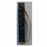
People also bought...
Doepfer A-130-2v VCAs Dual Linear/Exponential VCA Slim Line Series Vintage Edition Module (black) (dual/stereo/VCA synth module)
Cat: 973749 Rel: 14 Nov 23
Dual linear/exponential VCA module - 4HP.
Notes: Module A-130-2v is composed of two identical voltage controlled amplifiers (VCA). Each VCA has a manual gain control (also named Initial Gain) and a control voltage input with attenuator. The character of the control scale can be switched to linear or exponential. All inputs and outputs are DC coupled. Consequently the VCAs can be used to process both audio and control voltages (e.g. for voltage control of the level of LFO or envelope signals). The signal input has no attenuator available but is capable to process up to 16Vpp signals (i.e. -8V...+8V) without distortion. For the processing of higher levels an external attenuator (e.g. A-183-1) is recommended.
The amplification range is 0...1. Even with a higher external control voltage the amplification remains at 1 (kind of "amplification clipping" at 1).
Controls (for each of both units):
Gain: manual gain control (Initial Gain) in the range 0...1
CV: attenuator for the CV input
lin/exp: switches the VCA characteristic to linear or exponential, in center position the VCA is off (mute function)
Inputs and outputs (for each of both units):
CV: control voltage input, min. +5V required for max. amplification (1) with CV control fully CW and Gain fully CCW
In: signal input, max. 16Vpp (+8V...-8V) without distortion
Out: signal output
A-130-2v is the slim version of module A-132-3 and offers essentially the same features. But the distances between the controls are smaller and rubberized small-sized knobs are used. In return the front panel has 4 HP only which is half the width of the A-132-3. The module is primarily planned for applications where only limited space is available.
Power consumption: 30mA at +12V and 30mA at -12V
Depth: 50mm
HP : 4
… Read moreThe amplification range is 0...1. Even with a higher external control voltage the amplification remains at 1 (kind of "amplification clipping" at 1).
Controls (for each of both units):
Gain: manual gain control (Initial Gain) in the range 0...1
CV: attenuator for the CV input
lin/exp: switches the VCA characteristic to linear or exponential, in center position the VCA is off (mute function)
Inputs and outputs (for each of both units):
CV: control voltage input, min. +5V required for max. amplification (1) with CV control fully CW and Gain fully CCW
In: signal input, max. 16Vpp (+8V...-8V) without distortion
Out: signal output
A-130-2v is the slim version of module A-132-3 and offers essentially the same features. But the distances between the controls are smaller and rubberized small-sized knobs are used. In return the front panel has 4 HP only which is half the width of the A-132-3. The module is primarily planned for applications where only limited space is available.
Power consumption: 30mA at +12V and 30mA at -12V
Depth: 50mm
HP : 4
2 in stock $94.89
Click for better price!
or call +44 20 7424 1960
quote 973749
quote 973749
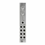
People also bought...
Notes: Module A-130-4 contains four linear VCAs with a common level control section for all four VCAs. It can be used for all applications of simultaneous amplitude/level control of up to four different audio or CV signals. A-130-4 is the replacement of the no longer available module A-132-2. Compared to the A-132-2 the width has been reduced from 8HP to 4HP.
The module has these controls and in/outputs available:
Control Man.: manual control of the amplification
Control CV: attenuator for the control voltage applied to socket CVo socket Input 1
Sockets In 1...4: VCA inputs 1...4
Sockets Out 1...4: VCA outputs 1...4
Application examples:
simultaneous amplitude/level control of up to four different audio or CV signals
polyphonic application 1: simultaneous control of the frequency modulation depth of 4 VCOs (Quad-LFO A-145-4 or Quad-VCLFO A-147-5 > A-130-4 > FM inputs A-111-4)
polyphonic application 2: simultaneous control of the pulsewidth modulation depth of 4 VCOs (Quad-LFO A-145-4 or Quad-VCLFO A-147-5 > A-130-4 > PWM inputs A-111-4)
simultaneous control of quadrophonic signals
Technical notes:
The maximum amplification for each VCA is about 1 ("Man." control fully CW). Even with an external control voltage applied to the CV input the maximum amplification is limited to 1.
The module is equipped with two internal connectors (pin headers with 4 pins each). Pin header #1 can be used to normalize the four inputs to other modules (e.g. Quad LFO A-145-4 or A-147-5, Quad ADSR A-143-2). Pin header #2 can be used to connect the four outputs to other modules.
The max. level at the VCA inputs without clipping/distortion is about 20Vpp or +/-10V.
Dimensions
4 HP
45 mm deep
… Read moreThe module has these controls and in/outputs available:
Control Man.: manual control of the amplification
Control CV: attenuator for the control voltage applied to socket CVo socket Input 1
Sockets In 1...4: VCA inputs 1...4
Sockets Out 1...4: VCA outputs 1...4
Application examples:
simultaneous amplitude/level control of up to four different audio or CV signals
polyphonic application 1: simultaneous control of the frequency modulation depth of 4 VCOs (Quad-LFO A-145-4 or Quad-VCLFO A-147-5 > A-130-4 > FM inputs A-111-4)
polyphonic application 2: simultaneous control of the pulsewidth modulation depth of 4 VCOs (Quad-LFO A-145-4 or Quad-VCLFO A-147-5 > A-130-4 > PWM inputs A-111-4)
simultaneous control of quadrophonic signals
Technical notes:
The maximum amplification for each VCA is about 1 ("Man." control fully CW). Even with an external control voltage applied to the CV input the maximum amplification is limited to 1.
The module is equipped with two internal connectors (pin headers with 4 pins each). Pin header #1 can be used to normalize the four inputs to other modules (e.g. Quad LFO A-145-4 or A-147-5, Quad ADSR A-143-2). Pin header #2 can be used to connect the four outputs to other modules.
The max. level at the VCA inputs without clipping/distortion is about 20Vpp or +/-10V.
Dimensions
4 HP
45 mm deep
1 in stock $81.33
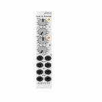
People also bought...
Doepfer A-133-2 Dual Voltage Controlled VCA/Polarizer/Inverter/Ring Modulator Module (silver) (attenuator/dual/stereo/polarizer/ring modulator/VCA synth module)
Cat: 765897 Rel: 28 Jul 20
VCA/polarizer/inverter/ring modulator module
Notes: A-133-2 is the slim version of the A-133 but has some additional features and improvements available compared to the A-133.
Module A-133-2 can be used for a lot of applications: as a simple VCA, or a voltage controlled polarizer/attuverter, or a voltage controlled inverter up to a DC coupled ring modulator. In principle the module contains two special voltage controlled amplifiers (VCAs) that allow both positive and negative amplification.
The overall amplification is definded by the sum of the voltage generated by the Man control, the external control voltage CV and the position of the CV control which works as an attenuator for the external control voltage. Without external CV the amplification is +1 when the Man control is fully CW. In the center position the amplification is zero and fully CCW it's -1 (i.e. the incoming signal is inverted). By means of the external control voltage CV the manually adjusted amplification can be modulated. CV can be both positive or negative (i.e. bipolar) to obtain positive or negative amplification values controlled by the external CV.
In addition the CV signal can be modulated via the modulation control input Mod by means of another control voltage. The Mod socket is normalled to +5V, i.e. a constant positive voltage is used as modulation CV provided that no plug is inserted into the Mod socket.
The current amplification is displayed by a dual color LED (note: it's not a signal display but indicates the amplification, probably yellow = positive amplification, red = negative amplification)
Application examples:
voltage controlled amplifier (VCA) with pure positive overall amplification (Man + CV)
voltage controlled inverter with pure negative overall amplification (Man + CV)
voltage controlled polarizer/attuverter overall amplification changing between positive and negative (Man + CV)
DC coupled ring modulator with offset feature, the "classical" ring modulator corresponds to Man=0 and symmetrical audio signals for In and CV
additional effects by means of the modulation feature of the CV signal (using the Mod input)
… Read moreModule A-133-2 can be used for a lot of applications: as a simple VCA, or a voltage controlled polarizer/attuverter, or a voltage controlled inverter up to a DC coupled ring modulator. In principle the module contains two special voltage controlled amplifiers (VCAs) that allow both positive and negative amplification.
The overall amplification is definded by the sum of the voltage generated by the Man control, the external control voltage CV and the position of the CV control which works as an attenuator for the external control voltage. Without external CV the amplification is +1 when the Man control is fully CW. In the center position the amplification is zero and fully CCW it's -1 (i.e. the incoming signal is inverted). By means of the external control voltage CV the manually adjusted amplification can be modulated. CV can be both positive or negative (i.e. bipolar) to obtain positive or negative amplification values controlled by the external CV.
In addition the CV signal can be modulated via the modulation control input Mod by means of another control voltage. The Mod socket is normalled to +5V, i.e. a constant positive voltage is used as modulation CV provided that no plug is inserted into the Mod socket.
The current amplification is displayed by a dual color LED (note: it's not a signal display but indicates the amplification, probably yellow = positive amplification, red = negative amplification)
Application examples:
voltage controlled amplifier (VCA) with pure positive overall amplification (Man + CV)
voltage controlled inverter with pure negative overall amplification (Man + CV)
voltage controlled polarizer/attuverter overall amplification changing between positive and negative (Man + CV)
DC coupled ring modulator with offset feature, the "classical" ring modulator corresponds to Man=0 and symmetrical audio signals for In and CV
additional effects by means of the modulation feature of the CV signal (using the Mod input)
1 in stock $98.02
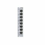
People also bought...
Doepfer A-134-2 Dual Voltage Controlled Crossfader Module (VCA/dual/stereo/panning synth module)
Cat: 716922 Rel: 29 Jan 19
Dual crossfader module for voltage controlled morphing between two audio or CV signals
Notes: Module A-134-2 contains two identical voltage controlled crossfader units.
Each unit has two voltage controlled amplifiers (VCAs) with opposite control behaviour available. The outputs of the two VCAs are mixed together to obtain a common output. The behaviour of the control voltage inputs can be chosen with an internal jumper:
Symmetrical mode: If the corresponding jumper is not set both VCAs of the crossfader have the same 50% amplification with zero CV. If the applied CV becomes positive the amplification of VCA1 decreases and those of VCA2 increases in the same way. A negative CV has the opposite result. The CV voltage range to obtain the maximum/minimum positions of the crossfader is about -2.5....+2.5V. This mode is useful for bidirectional (i.e. positive and negative) control voltages, for example LFO or joy stick (adjusted to 0V CV in centre position).
Asymmetrical mode: If the corresponding jumper is set VCA2 is fully closed and VCA1 has full 100% amplification with zero CV. If the applied CV becomes positive the amplification of VCA1 decreases and those of VCA2 increases in the same way. The CV voltage range to obtain the maximum/minimum positions of the crossfader is about 0...+5V. A negative CV has no function in this mode. This mode is useful for unidirectional (i.e. only positive) control voltages, for example ADSR, ribbon controller or Theremin control voltage.
The CV input of the upper unit (CV1) is normalled to the CV input of the lower unit (CV2). I.e. if no plug is inserted to CV2 the CV input of the upper unit (CV1) also controls the lower unit.
The second signal input of the upper unit (In1B) is normalled to the first signal input of the lower unit (In2A). I.e. if no plug is inserted into In2A the signal In1B is used as the first signal input of the second unit.
As the inputs and outputs are DC coupled the module can be used for both audio and control voltage signal processing.
… Read moreEach unit has two voltage controlled amplifiers (VCAs) with opposite control behaviour available. The outputs of the two VCAs are mixed together to obtain a common output. The behaviour of the control voltage inputs can be chosen with an internal jumper:
Symmetrical mode: If the corresponding jumper is not set both VCAs of the crossfader have the same 50% amplification with zero CV. If the applied CV becomes positive the amplification of VCA1 decreases and those of VCA2 increases in the same way. A negative CV has the opposite result. The CV voltage range to obtain the maximum/minimum positions of the crossfader is about -2.5....+2.5V. This mode is useful for bidirectional (i.e. positive and negative) control voltages, for example LFO or joy stick (adjusted to 0V CV in centre position).
Asymmetrical mode: If the corresponding jumper is set VCA2 is fully closed and VCA1 has full 100% amplification with zero CV. If the applied CV becomes positive the amplification of VCA1 decreases and those of VCA2 increases in the same way. The CV voltage range to obtain the maximum/minimum positions of the crossfader is about 0...+5V. A negative CV has no function in this mode. This mode is useful for unidirectional (i.e. only positive) control voltages, for example ADSR, ribbon controller or Theremin control voltage.
The CV input of the upper unit (CV1) is normalled to the CV input of the lower unit (CV2). I.e. if no plug is inserted to CV2 the CV input of the upper unit (CV1) also controls the lower unit.
The second signal input of the upper unit (In1B) is normalled to the first signal input of the lower unit (In2A). I.e. if no plug is inserted into In2A the signal In1B is used as the first signal input of the second unit.
As the inputs and outputs are DC coupled the module can be used for both audio and control voltage signal processing.
1 in stock $72.99
Click for better price!
or call +44 20 7424 1960
quote 716922
quote 716922
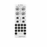
People also bought...
Doepfer A-135-2 Quad VCA & Voltage Controller Mixer Module (silver) (mixer/quad/VCA synth module)
Cat: 714704 Rel: 22 Jan 19
Compact voltage-controlled four-channel audio mixer - 8HP
Notes: A-135-2 is a miniature version of the A-135-1. Behind a front panel with 8 HP only four linear VCAs (voltage controlled amplifiers) and a voltage controlled mixer based on the VCAs are available.
Controls, In/Outputs and Functions of each VCA:
- Level (manual control of the VCA amplification), small rubberized knob (L1...L4)
- Control voltage input with associated attenuator (CV1...CV4), for the full VCA control range about 0...+5V control voltage are required (attenuator fully clockwise), for higher control voltages the attenuator is used, the attenuators are without knobs, just plastic shafts with white marker
- Signal Input
- Signal Output
- All inputs and outputs are DC coupled. Consequently the VCAs can be used to process both audio and control voltages (e.g. to control the level of LFOs or envelopes)
- The signal input is not equipped with an attenuator. But the VCAs can process all signals up to 15Vpp / -7.5...+7.5V without clipping. In case of higher levels an external attenuator is required (e.g. A-183-1).
- The available amplification range is 0...1, the maximal amplification is 1 (i.e. it "clips" and remains at 1 even if the control voltage goes beyond the value that corresponds to amplification 1)
Functions of the voltage controlled mixers:
- Two outputs ("Selected" and "All")
- Selected output: the ouput if a VCA is removed from this sum signal when a plug is inserted into the corresponding VCA output.
- All output: sum of all VCA outputs, regardless of inserted plugs into the VCA outputs
- The maximal amplification is about 0.6 to avoid clipping at the mixer outputs (otherwise the outputs may distort with 15Vpp signals at each signal input and full amplifications)
Special functions of the voltage controlled mixers (selectable by internal jumpers):
- Dual Stereo VCA: In this case the control unit of VCA1 (L1 + CV1) affects also VCA3 and the control unit of VCA2 (L2 + CV2) affects also VCA4, the control units of VCA2 and VCA4 are out of operation
- Quad VCA: In this case the control unit of VCA1 (L1 + CV1) affects all four VCAs. The control units of VCA2, VCA3 and VCA4 are out of operation. In this mode the module has the same function as module A-132-2. That's why module A-132-2 will be discontinued.
- Normalling of the signal inputs: by means of internal jumpers signal input 1 can be normalled to signal input 2, signal input 2 to signal input 3 and signal input 3 to signal input In 4. That way the same input signal can be distributed to four different channels by means of control voltages (e.g. quadrophonic distribution of audio signals). Suitable control voltage sources are e.g. A-144 (Morphing Controller) or A-143-9 (Quadrature LFO).
… Read moreControls, In/Outputs and Functions of each VCA:
- Level (manual control of the VCA amplification), small rubberized knob (L1...L4)
- Control voltage input with associated attenuator (CV1...CV4), for the full VCA control range about 0...+5V control voltage are required (attenuator fully clockwise), for higher control voltages the attenuator is used, the attenuators are without knobs, just plastic shafts with white marker
- Signal Input
- Signal Output
- All inputs and outputs are DC coupled. Consequently the VCAs can be used to process both audio and control voltages (e.g. to control the level of LFOs or envelopes)
- The signal input is not equipped with an attenuator. But the VCAs can process all signals up to 15Vpp / -7.5...+7.5V without clipping. In case of higher levels an external attenuator is required (e.g. A-183-1).
- The available amplification range is 0...1, the maximal amplification is 1 (i.e. it "clips" and remains at 1 even if the control voltage goes beyond the value that corresponds to amplification 1)
Functions of the voltage controlled mixers:
- Two outputs ("Selected" and "All")
- Selected output: the ouput if a VCA is removed from this sum signal when a plug is inserted into the corresponding VCA output.
- All output: sum of all VCA outputs, regardless of inserted plugs into the VCA outputs
- The maximal amplification is about 0.6 to avoid clipping at the mixer outputs (otherwise the outputs may distort with 15Vpp signals at each signal input and full amplifications)
Special functions of the voltage controlled mixers (selectable by internal jumpers):
- Dual Stereo VCA: In this case the control unit of VCA1 (L1 + CV1) affects also VCA3 and the control unit of VCA2 (L2 + CV2) affects also VCA4, the control units of VCA2 and VCA4 are out of operation
- Quad VCA: In this case the control unit of VCA1 (L1 + CV1) affects all four VCAs. The control units of VCA2, VCA3 and VCA4 are out of operation. In this mode the module has the same function as module A-132-2. That's why module A-132-2 will be discontinued.
- Normalling of the signal inputs: by means of internal jumpers signal input 1 can be normalled to signal input 2, signal input 2 to signal input 3 and signal input 3 to signal input In 4. That way the same input signal can be distributed to four different channels by means of control voltages (e.g. quadrophonic distribution of audio signals). Suitable control voltage sources are e.g. A-144 (Morphing Controller) or A-143-9 (Quadrature LFO).
1 in stock $124.09
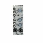
People also bought...
Doepfer A-138d Crossfader/FX Insert Module (external/mixer synth module)
Cat: 716947 Rel: 29 Jan 19
Crossfader for two different A-100 signals, plus insert for external effects
Notes: The A-138d primarily is used for crossfading between two modular signals. On the other hand you can used it for inserting stompboxes or other effects into your modular system. Both the inputs and the mix output are available twice, like a mini-multiples e.g. for using the input signal also for other applications, kind of like a Thru.
Crossfader: With the crossfading control CF you blend manually between the inputs In 1 and In 2. The Mute switch allows for muting one of the two signals, independent on the crossfader position.
Effect insert: The signal at input In1 is emitted at the FX Send output and can be attenuated with the Atten. control because the modular system works with much higher levels.
The effect unit's output is inserted to the FX Return input socket and its level can be boosted with the Amp. control. The processed signal is available at the bottom in 2 socket.
Use the CF control to blend between the original signal and the effect signal and to mute switch for quick muting e.g. of the effect return signal.
… Read moreCrossfader: With the crossfading control CF you blend manually between the inputs In 1 and In 2. The Mute switch allows for muting one of the two signals, independent on the crossfader position.
Effect insert: The signal at input In1 is emitted at the FX Send output and can be attenuated with the Atten. control because the modular system works with much higher levels.
The effect unit's output is inserted to the FX Return input socket and its level can be boosted with the Amp. control. The processed signal is available at the bottom in 2 socket.
Use the CF control to blend between the original signal and the effect signal and to mute switch for quick muting e.g. of the effect return signal.
1 in stock $68.81
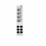
People also bought...
Doepfer A-138n Narrow Mini Mixer Slim Line Series Module (silver) (quad/mixer synth module)
Cat: 731947 Rel: 10 Jun 19
Compact 4-channel mixer - 4HP
Notes: Module A-138n is a simple four channel mixer, which can be used with either control voltages or audio signals. Each of the four inputs has an attenuator available. The output is twice available (two sockets, hard-wired like a multiple).
The module is the slim version of module A-138a and offers nearly the same features. But the distances between the controls are smaller and rubberized small-sized knobs are used. In return the front panel has 4 HP only which is half the width of the A-138a. The module is primarily planned for applications where only limited space is available. The only functional difference compared to the A-138a is the missing attenuator for the (dual) output.
… Read moreThe module is the slim version of module A-138a and offers nearly the same features. But the distances between the controls are smaller and rubberized small-sized knobs are used. In return the front panel has 4 HP only which is half the width of the A-138a. The module is primarily planned for applications where only limited space is available. The only functional difference compared to the A-138a is the missing attenuator for the (dual) output.
1 in stock $55.22
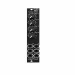
People also bought...
Doepfer A-138nv Narrow Mini Mixer Vintage Edition Module (black) (mixer/quad synth module)
Cat: 760211 Rel: 06 Mar 20
Narrow mini mixer module - 4HP.
Notes: Compact and simple four-input mixer module from Uncle Dieter. Linear pots make it suited to mixing CV signals but it can also handle audio. Mixed signal hard-wired to two sockets.
Supplier notes:
Module A-138n is a simple four channel mixer, which can be used with either control voltages or audio signals. Each of the four inputs has an attenuator available. The output is twice available (two sockets, hard-wired like a multiple).
HP : 4
… Read moreSupplier notes:
Module A-138n is a simple four channel mixer, which can be used with either control voltages or audio signals. Each of the four inputs has an attenuator available. The output is twice available (two sockets, hard-wired like a multiple).
HP : 4
1 in stock $63.40
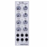
People also bought...
Doepfer A-138s Mini Stereo Mixer Module (silver) (mixer/panning/dual/stereo/quad synth module)
Cat: 671589 Rel: 29 Nov 17
Four-channel stereo mixer - 8HP
Notes: A-138s is a simple but useful 4-in-2 mixing tool. It has four inputs available. Each input is equipped with an attenuator (Level) and a panning control that is used to distribute the signal to the left and right output. Beyond stereo mixing it is equally suited to create variable parallel routings. For example: Any of the four inputs may be routed in variable intensity to feed two filters.
You may regard the A-138s as a smaller version of the A-138m Matrix Mixer.
Inputs and outputs are DC coupled, i.e. the module can be used for the mixing of control signals too.
- 3U Eurorack module, 8 HP wide, 30 mm in depth
- Power consumption: 10 mA at +12 V and 10 mA at -12 V
… Read moreYou may regard the A-138s as a smaller version of the A-138m Matrix Mixer.
Inputs and outputs are DC coupled, i.e. the module can be used for the mixing of control signals too.
- 3U Eurorack module, 8 HP wide, 30 mm in depth
- Power consumption: 10 mA at +12 V and 10 mA at -12 V
1 in stock $78.20
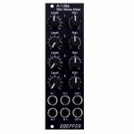
People also bought...
Doepfer A-138sv Mini Stereo Mixer Vintage Edition Module (black) (dual/stereo/mixer/panning/quad synth module)
Cat: 684443 Rel: 30 Apr 18
Four-channel stereo mixer - 8HP
Notes: A-138s is a simple but useful 4-in-2 mixing tool. It has four inputs available. Each input is equipped with an attenuator (Level) and a panning control that is used to distribute the signal to the left and right output. Beyond stereo mixing it is equally suited to create variable parallel routings. For example: Any of the four inputs may be routed in variable intensity to feed two filters.
You may regard the A-138s as a smaller version of the A-138m Matrix Mixer.
Inputs and outputs are DC coupled, i.e. the module can be used for the mixing of control signals too.
- 3U Eurorack module, 8 HP wide, 30 mm in depth
- Power consumption: 10 mA at +12 V and 10 mA at -12 V
… Read moreYou may regard the A-138s as a smaller version of the A-138m Matrix Mixer.
Inputs and outputs are DC coupled, i.e. the module can be used for the mixing of control signals too.
- 3U Eurorack module, 8 HP wide, 30 mm in depth
- Power consumption: 10 mA at +12 V and 10 mA at -12 V
4 in stock $85.51
Click for better price!
or call +44 20 7424 1960
quote 684443
quote 684443
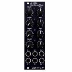
People also bought...
Doepfer A-138sv Mini Stereo Mixer Vintage Edition Module (black) (B-STOCK) (dual/stereo/mixer/panning/quad synth module)
Cat: 980376 Rel: 01 Jan 90
B-STOCK: Item refurbished, repaired and in perfect working order.
Notes: ***B-STOCK: Item refurbished, repaired and in perfect working order.***
A-138s is a simple but useful 4-in-2 mixing tool. It has four inputs available. Each input is equipped with an attenuator (Level) and a panning control that is used to distribute the signal to the left and right output. Beyond stereo mixing it is equally suited to create variable parallel routings. For example: Any of the four inputs may be routed in variable intensity to feed two filters.
You may regard the A-138s as a smaller version of the A-138m Matrix Mixer.
Inputs and outputs are DC coupled, i.e. the module can be used for the mixing of control signals too.
- 3U Eurorack module, 8 HP wide, 30 mm in depth
- Power consumption: 10 mA at +12 V and 10 mA at -12 V
… Read moreA-138s is a simple but useful 4-in-2 mixing tool. It has four inputs available. Each input is equipped with an attenuator (Level) and a panning control that is used to distribute the signal to the left and right output. Beyond stereo mixing it is equally suited to create variable parallel routings. For example: Any of the four inputs may be routed in variable intensity to feed two filters.
You may regard the A-138s as a smaller version of the A-138m Matrix Mixer.
Inputs and outputs are DC coupled, i.e. the module can be used for the mixing of control signals too.
- 3U Eurorack module, 8 HP wide, 30 mm in depth
- Power consumption: 10 mA at +12 V and 10 mA at -12 V
1 in stock $78.07
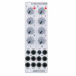
People also bought...
Doepfer A-140-2 Dual Micro ADSR Module (silver) (dual/stereo/envelope generator synth module)
Cat: 684450 Rel: 18 Jul 18
Dual ADSR envelope generator - 8HP
Notes: Module A-140-2 contains two ADSR type envelope generators behind a front panel with 8 HP only.
Each ADSR provides these controls and in/outputs:
- LED (displays the envelope output)
- A: manual Attack control
- D: manual Decay control
- S: manual Sustain control
- R: manual Release control
- Gate Input
- Retrigger Input
- CVT Input with attenuator (CVT = CV Time)
- Envelope Output 1
- Envelope Output 2
The output voltage range for each envelope is 0 - 10V. The time range of Attack/Decay/Release is about 1ms to 30s.
By means of internal jumpers one can select which time parameters are controlled by the CVT input (e.g. D only or D+R or A+D+R) and in which direction (i.e. if an increasing CVT shortens or stretches the time parameter in question).
Socket CVT can be normalled to an internal fixed voltage (i.e. the switching contact is connected to an internal fixed voltage). That way it's possible to change all time parameters simultaneously by means of the CVT control.
Another jumper is used to set output 2 to normal or inverted envelope.
And another jumper is used for the normalling of Gate 2 to Gate 1 (i.e. ADSR#2 is also triggered by Gate 1).
Two more jumpers are used for the optional bus access to the gate signal of the bus for each ADSR. Changing the positions of the mentioned jumpers allows to modify the factory settings.
… Read moreEach ADSR provides these controls and in/outputs:
- LED (displays the envelope output)
- A: manual Attack control
- D: manual Decay control
- S: manual Sustain control
- R: manual Release control
- Gate Input
- Retrigger Input
- CVT Input with attenuator (CVT = CV Time)
- Envelope Output 1
- Envelope Output 2
The output voltage range for each envelope is 0 - 10V. The time range of Attack/Decay/Release is about 1ms to 30s.
By means of internal jumpers one can select which time parameters are controlled by the CVT input (e.g. D only or D+R or A+D+R) and in which direction (i.e. if an increasing CVT shortens or stretches the time parameter in question).
Socket CVT can be normalled to an internal fixed voltage (i.e. the switching contact is connected to an internal fixed voltage). That way it's possible to change all time parameters simultaneously by means of the CVT control.
Another jumper is used to set output 2 to normal or inverted envelope.
And another jumper is used for the normalling of Gate 2 to Gate 1 (i.e. ADSR#2 is also triggered by Gate 1).
Two more jumpers are used for the optional bus access to the gate signal of the bus for each ADSR. Changing the positions of the mentioned jumpers allows to modify the factory settings.
1 in stock $140.77
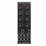
People also bought...
Doepfer A-140-2v Dual Mini ADSR Vintage Edition Module (black) (dual/stereo/envelope generator synth module)
Cat: 734880 Rel: 10 Jul 19
Envelope module with two ADSR voltage controlled enevelope generators - 8HP
Notes: The module contains two ADSR type voltage controlled envelope generators with exponential curve shapes (charge/discharge curves of a capacitor) behind a front panel with 8 HP only.
Each ADSR provides these controls and in/outputs:
- LED (displays the envelope output)
- A: manual Attack control
- D: manual Decay control
- S: manual Sustain control
- R: manual Release control
- Gate Input
- Retrigger Input
- CVT Input with attenuator (CVT = CV Time)
- Envelope Output 1
- Envelope Output 2
The output voltage range for each envelope is 0 - 10V (10V = attack peak).
The time range of Attack/Decay/Release is about 1ms to 30s.
By means of internal jumpers one can select which time parameters are controlled by the CVT input (e.g. D only or D+R or A+D+R) and in which direction (i.e. if an increasing CVT shortens or stretches the time parameter in question).
Socket CVT can be normalled to an internal fixed voltage (i.e. the switching contact is connected to an internal fixed voltage). That way it's possible to change all time parameters simultaneously by means of the CVT control.
Another jumper is used to set output 2 to normal or inverted envelope.
And another jumper is used for the normalling of Gate 2 to Gate 1 (i.e. ADSR#2 is also triggered by Gate 1).
Two more jumpers are used for the optional bus access to the gate signal of the bus for each ADSR.
… Read moreEach ADSR provides these controls and in/outputs:
- LED (displays the envelope output)
- A: manual Attack control
- D: manual Decay control
- S: manual Sustain control
- R: manual Release control
- Gate Input
- Retrigger Input
- CVT Input with attenuator (CVT = CV Time)
- Envelope Output 1
- Envelope Output 2
The output voltage range for each envelope is 0 - 10V (10V = attack peak).
The time range of Attack/Decay/Release is about 1ms to 30s.
By means of internal jumpers one can select which time parameters are controlled by the CVT input (e.g. D only or D+R or A+D+R) and in which direction (i.e. if an increasing CVT shortens or stretches the time parameter in question).
Socket CVT can be normalled to an internal fixed voltage (i.e. the switching contact is connected to an internal fixed voltage). That way it's possible to change all time parameters simultaneously by means of the CVT control.
Another jumper is used to set output 2 to normal or inverted envelope.
And another jumper is used for the normalling of Gate 2 to Gate 1 (i.e. ADSR#2 is also triggered by Gate 1).
Two more jumpers are used for the optional bus access to the gate signal of the bus for each ADSR.
1 in stock $138.08
