100% Sicheres Einkaufen
Studio equipment
Our full range of studio equipment from all the leading equipment and software brands. Guaranteed fast delivery and low prices.
100% Sicheres Einkaufen
DJ equipment
Our full range of DJ equipment from all the leading equipment and software brands. Guaranteed fast delivery and low prices. Visit Juno DJ

Hilfe
BestellenProbleme beim BestellenHäufig gestellte FragenKontaktiere unsKontaktiere uns (Lieferanten)Über JunoJuno DailyNew This WeekDJ & Studio StoreTagsFeedbackDatenschutzregelungReturns & refundsAGBFinanceJuno Vinyl DistributionJuno Vinyl WholesaleJuno Marketing and PR departmentPromote your label / releases


Filter
Stock

Coming Soon
Equipment
Format
Brand
Featured
Price
Tags
Options
Sort
Date
Date
- Relevance:
- Most relevant
- Bestseller:
- Absteigend sortieren
- Artist:
- Alphabetisch sortieren (aufsteigend)
- Alphabetisch sortieren (absteigend)
- Title:
- Alphabetisch sortieren (aufsteigend)
- Alphabetisch sortieren (absteigend)
- Label:
- Alphabetisch sortieren (aufsteigend)
- Alphabetisch sortieren (absteigend)
- Date:
- Nach Alter sortieren (absteigend)
- Nach Alter sortieren (aufsteigend)
- Price:
- Nach Preis sortieren (aufsteigend)
- Nach Preis sortieren (absteigend)
FORTHCOMING
Related products...
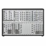
Doepfer A-100 Basic System 3 Full Analogue Modular System (LC6v case with PSU) (analogue modular synthesiser)
Cat: 982339 • View all Synthesisers
Full analogue modular system
Notes: The new basic system 3 from Doepfer is a return to Dieter Doepfer's original vision of analogue modular synthesis. Modules can be connected via front panel audio and CV connectors and used in infinite combinations. The Basic System 3 is an easily accessible and well-structured system that can be used by enthusiasts and beginners alike. It can be used as a base for exploring sound synthesis and electronic sounds, or as a supplement to delve deeper into different types of synthesis. For example, it is possible to create 4-part paraphonic patches or create complex sounds using the ring modulator. Percussion and drum sounds can also be created in a variety of ways alongside the classic synth sounds. The system's two filters can also be set to self-resonance to provide additional sound sources. The Waveshaper can be used to modify simple sounds and change their overall timbre. As each user's personal requirements are different, blank panels are installed that can be replaced with modules. This means there is no need to buy a new cabinet.
The following modules are included in the basic system 3:
1x A-108 6/12/24/48dB Low Pass Filter
2x A-110-1 Standard VCO
1x A-118 Noise / Random
1x A-121-2 Multimode Filter
1x A-131 VCA exponential
1x A-132-3 Dual linear/exponential VCA
1x A-137-1 Wave Multiplier I
1x A-138j Inverting/Interrupting Mixer (Janus Mixer)
1x A-138b Mixer logarithm.
1x A-138s Mini Stereo Mixer
1x A-140 ADSR Envelope Generator
1x A-140-2 Dual Mini-ADSR
1x A-147-4 Dual VCLFO
1x A-151 Quad Sequential Switch
1x A-160-2 Clock Divider II
1x A-171-2 VC Slew Processor / Generator
2x A-180-2 Multiples 1
1x A-184-1 Ring Modulator/S+H/T+H/Slew Limiter
5x Blind Panel 4HP
The following Patch cables are included:
5x A-100C15 Cable 15cm yellow
10x A-100C30 Cable 30cm black
15x A-100C50 Cable 50cm grey
5x A-100C80 Cable 80cm red
… Read moreThe following modules are included in the basic system 3:
1x A-108 6/12/24/48dB Low Pass Filter
2x A-110-1 Standard VCO
1x A-118 Noise / Random
1x A-121-2 Multimode Filter
1x A-131 VCA exponential
1x A-132-3 Dual linear/exponential VCA
1x A-137-1 Wave Multiplier I
1x A-138j Inverting/Interrupting Mixer (Janus Mixer)
1x A-138b Mixer logarithm.
1x A-138s Mini Stereo Mixer
1x A-140 ADSR Envelope Generator
1x A-140-2 Dual Mini-ADSR
1x A-147-4 Dual VCLFO
1x A-151 Quad Sequential Switch
1x A-160-2 Clock Divider II
1x A-171-2 VC Slew Processor / Generator
2x A-180-2 Multiples 1
1x A-184-1 Ring Modulator/S+H/T+H/Slew Limiter
5x Blind Panel 4HP
The following Patch cables are included:
5x A-100C15 Cable 15cm yellow
10x A-100C30 Cable 30cm black
15x A-100C50 Cable 50cm grey
5x A-100C80 Cable 80cm red
Pre-orders at Juno
This product is available for pre-order at Juno, for shipping on the release date. You won’t be charged until the order is despatched.
We'll keep you informed of your order at every stage, and let you know if the release date changes.
If the price of the item drops before it's released, you will pay the lower price, but if it increases, you'll only pay the price you see today.
If you also include in-stock items on your order, they’ll be charged and shipped within 24 hours as usual.coming soon $2,653.47
(No payment required now - pay when released)
People also bought...
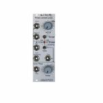
Doepfer A-196 PLL Phase Locked Loop Module (B-STOCK) (filter/oscillator/effect synth module)
Cat: 994989 Rel: 01 Jan 90 • View all Synth modules
B-STOCK: Box damaged, product in perfect working order
Notes: ***B-STOCK: Box damaged, product in perfect working order***
Module A-196 contains a so-called phase locked loop (PLL). The basic PLL system is shown in the sketch at the bottom of this page. A PLL consists of three parts: voltage-controlled oscillator (VCO), phase comparator (PC), and low-pass filter (LPF). All parts are normally connected to form a closed-loop frequency-feedback system.
This is how a PLL works: The output of the internal VCO (linear CV control, rectangle output) is compared with an external signal (e.g. the rectangle output of a A-110 VCO) in the so-called phase comparator (PC). The output of the phase comparator is a digital signal (low/high/tristate) that indicates if the frequency resp. phase difference of the two input signals is negative, zero or positive. The output of the phase comparator is processed by a low pass filter (LPF) to generate a smooth voltage that is used to control the frequency of the internal VCO. The 3 units VCO, PC and LPF form a feedback loop that works like this: The control voltage (output of the LPF) increases as long as the external frequency is higher than the frequency of the internal VCO und stops increasing when both frequencies become identical. The control voltage decreases as long as the external frequency is lower than the frequency of the internal VCO und stops decreasing when both frequencies become identical.
But there are some stumbling blocks: Different types of phase comparators with advantages and disadvantages can be made. Some phase comparators e.g. even lock at harmonics, i.e. if the two frequencies to be compared are integer multiples. But for some applications this can be used to create interesting effects. The A-196 contains 3 different types of phase comparators: PC1 is a simple exclusive OR, that even locks at harmonics. PC2 is a so-called RS flipflop and PC3 a more complex digital memory network. The user can select one of the three phase comparators with a 3-position switch. When PC2 is used a LED displays the "locked" state, i.e. when the frequency of the internal VCO is identical to the external frequency.
Special attention has to be directed to the frequency of the LPF. To obtain a smooth control voltage for the VCO the frequency of the LPF has to be much smaller than the lowest frequency of the internal or external audio signal. Otherwise the frequency of the internal VCO will jitter or wobble around the correct frequency. But for special effects this frequency jitter can be used intentionally. Example: frequencies in the range 50Hz...1kHz have to be processed with the PLL. Therefore the frequency of the LPF has to be about 10Hz or even less. Such a low frequency of the LPF causes a noticeable slew of the internal VCO. When the frequency of the external signal jumps e.g. between 500Hz and 1kHz it takes about 0.1 second until the internal VCO reaches the new frequency (like portamento). So one has to find a compromise between frequency jitter and portamento. But these remarks are valid only for the "ideal" working PLL. As the A-196 is used in a musical environment the "problems" and disadvantages with jitter and slew time lead to additional musical applications like portamento effects, wobbling frequencies or harmonic locking according to the type of frequency comparator and time constant of the PLL low pass filter. Instead of the internal manually controlled low pass filter the voltage controlled slew limiter A-171 can be used to obtain voltage control of this parameter. Normal audio filters (e.g. A-120, A-121) cannot be used for this job as the minimum frequency is to high (down to a few Hz or even less necessary) and the signal has to be DC coupled due to the low frequencies. Audio filters are normally AC coupled.
Another very important application of a PLL is frequency multiplication in combination with an external frequency divider. For this the output of the PLL-VCO is processed through an external frequency divider (e.g. A-163, A-160, A-161, A-115) before it is fed to In1 of the phase comparator. In this case the frequency of the PLL-VCO will be a multiple of the master frequency. E.g. if the A-163 is used and adjusted to dividing factor 5 the frequency of the PLL-VCO will be 5 times the frequency of the master VCO. Consequently, frequency division (A-163) leads to frequency multiplication with the PLL circuit. In combination with the PLL low pass frequency several effects can be realized (frequency multiplication with portamento or wobbling). The frequency multiplication can even be used to drive a graphic VCO. If your graphic VCO e.g. has 8 steps (e.g. A-155) and you use a frequency divider with factor 8 in the PLL feedback the output of the graphic VCO has the same frequency as the master VCO. Another application is the generation of pseudo-harmonics (not real harmonics as only rectangle waves are available) or clock generation for switched-capacitor filters.
… Read moreModule A-196 contains a so-called phase locked loop (PLL). The basic PLL system is shown in the sketch at the bottom of this page. A PLL consists of three parts: voltage-controlled oscillator (VCO), phase comparator (PC), and low-pass filter (LPF). All parts are normally connected to form a closed-loop frequency-feedback system.
This is how a PLL works: The output of the internal VCO (linear CV control, rectangle output) is compared with an external signal (e.g. the rectangle output of a A-110 VCO) in the so-called phase comparator (PC). The output of the phase comparator is a digital signal (low/high/tristate) that indicates if the frequency resp. phase difference of the two input signals is negative, zero or positive. The output of the phase comparator is processed by a low pass filter (LPF) to generate a smooth voltage that is used to control the frequency of the internal VCO. The 3 units VCO, PC and LPF form a feedback loop that works like this: The control voltage (output of the LPF) increases as long as the external frequency is higher than the frequency of the internal VCO und stops increasing when both frequencies become identical. The control voltage decreases as long as the external frequency is lower than the frequency of the internal VCO und stops decreasing when both frequencies become identical.
But there are some stumbling blocks: Different types of phase comparators with advantages and disadvantages can be made. Some phase comparators e.g. even lock at harmonics, i.e. if the two frequencies to be compared are integer multiples. But for some applications this can be used to create interesting effects. The A-196 contains 3 different types of phase comparators: PC1 is a simple exclusive OR, that even locks at harmonics. PC2 is a so-called RS flipflop and PC3 a more complex digital memory network. The user can select one of the three phase comparators with a 3-position switch. When PC2 is used a LED displays the "locked" state, i.e. when the frequency of the internal VCO is identical to the external frequency.
Special attention has to be directed to the frequency of the LPF. To obtain a smooth control voltage for the VCO the frequency of the LPF has to be much smaller than the lowest frequency of the internal or external audio signal. Otherwise the frequency of the internal VCO will jitter or wobble around the correct frequency. But for special effects this frequency jitter can be used intentionally. Example: frequencies in the range 50Hz...1kHz have to be processed with the PLL. Therefore the frequency of the LPF has to be about 10Hz or even less. Such a low frequency of the LPF causes a noticeable slew of the internal VCO. When the frequency of the external signal jumps e.g. between 500Hz and 1kHz it takes about 0.1 second until the internal VCO reaches the new frequency (like portamento). So one has to find a compromise between frequency jitter and portamento. But these remarks are valid only for the "ideal" working PLL. As the A-196 is used in a musical environment the "problems" and disadvantages with jitter and slew time lead to additional musical applications like portamento effects, wobbling frequencies or harmonic locking according to the type of frequency comparator and time constant of the PLL low pass filter. Instead of the internal manually controlled low pass filter the voltage controlled slew limiter A-171 can be used to obtain voltage control of this parameter. Normal audio filters (e.g. A-120, A-121) cannot be used for this job as the minimum frequency is to high (down to a few Hz or even less necessary) and the signal has to be DC coupled due to the low frequencies. Audio filters are normally AC coupled.
Another very important application of a PLL is frequency multiplication in combination with an external frequency divider. For this the output of the PLL-VCO is processed through an external frequency divider (e.g. A-163, A-160, A-161, A-115) before it is fed to In1 of the phase comparator. In this case the frequency of the PLL-VCO will be a multiple of the master frequency. E.g. if the A-163 is used and adjusted to dividing factor 5 the frequency of the PLL-VCO will be 5 times the frequency of the master VCO. Consequently, frequency division (A-163) leads to frequency multiplication with the PLL circuit. In combination with the PLL low pass frequency several effects can be realized (frequency multiplication with portamento or wobbling). The frequency multiplication can even be used to drive a graphic VCO. If your graphic VCO e.g. has 8 steps (e.g. A-155) and you use a frequency divider with factor 8 in the PLL feedback the output of the graphic VCO has the same frequency as the master VCO. Another application is the generation of pseudo-harmonics (not real harmonics as only rectangle waves are available) or clock generation for switched-capacitor filters.
out of stock $69.78
People also bought...
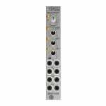
Doepfer A-147-5 Quad VCLFO Module (silver) (B-STOCK) (LFO synth module)
Cat: 991895 Rel: 01 Jan 90 • View all Synth modules
B-STOCK: Box opened, but product is in excellent condition and in perfect working order
Notes: ***B-STOCK: Box opened, but product is in excellent condition and in perfect working order***
Module A-147-5 contains four voltage controlled low frequency oscillators (VCLFO) with triangle waveform outputs. All LFOs share a common frequency control. Each of the LFOs 2, 3 features a Delta control which is used to shift the frequency of the LFO in question up or down. With the Delta controls at center positions the frequencies of all LFOs are roughly the same. To control the frequencies by external control voltages four CV inputs are available which follow roughly the 1V/oct standard.
The module has these controls and in/outputs available:
Control F: manual control of the frequency for all four LFOs
Control Delta F2, F3 and F4: manual control of the frequency shift up/down for the LFO in question
Sockets CV 1...4: Frequency control voltage inputs (normalled from top to bottom)
Sockets with triangle symbol 1...4: triangle outputs
LEDs: visual displays of the triangle outputs (red = positive, yellow = negative output voltage)
Application examples:
Generation of four triangle modulation signals with a common frequency control for all LFOs and individual controls for the frequency deviation of each LFO, manually adjustable and controllable by external control voltages
Generation of modulation signals for polyphonic FM/PWM applications. For this the four CV inputs are connected to the same control voltages which are used to control the frequencies of the corresponding VCOs. That way each LFO follows the frequency of the associated VCO with the possibility to control the frequency of all VCOs (control F) and the frequency deviations (Delta F controls). For the simultaneous modulation depth control the Quad VCA module A-130-4 is recommended.
Generation of complex modulation signals by summing up the outputs (e.g. by means of a mixer module A-138n / A-138i / A-138j)
Technical notes:
The level of the triangle outputs is about +/-5V (10Vpp)
The manually adjustable frequency ranges from about 0.025 Hz (about 40 seconds) to about 50 Hz with the delta controls of LFOs 2, 3 and 4 about center position
The frequency deviations adjusted by the delta controls are about +/-1:5. Example: with 1 Hz in center position the frequency shift ranges from about 0.2 Hz in position -5 to about 5 Hz in position +5 (1 Hz/5 = 0.2 Hz, 1 Hz*5 = 5 Hz).
The manual frequency controls and the control voltage inputs have an exponential control behavior
With external control voltage the max. frequency is about 150 Hz, the minimum frequency
The scale of the CV inputs is roughly 1V/oct (not adjustable)
The CV inputs are normalled from top to bottom. Provided that only socket CV1 is patched CV1 controls the frequencies of all four LFOs.
When each CV input is patched to it's own control voltage each LFO is controlled individually by it's own CV. In this case CV1 controls only the frequency of LFO1.
Internally the rectangle outputs are available at four terminals (typ level +/-10V or 20Vpp). If required they can be wired to four sockets of a DIY breakout module made by the user, 1k protection resistors are recommended to avoid short circuits. If lower levels are required passive attenuators (voltage dividers) may be used.
Internally is even an (unbufferd) triangle sum signal available. For this each of the four triangle outputs is simply connected to the sum output terminal via a 47k resistor. This output has high impedance and should be buffered or amplified to avoid level drop when the load changes (e.g. by means of an A-180-3 or A-180-4 or A-183-3).
By changing the values of the capacitors in the LFO circuits even other frequency ranges are possible (e.g. Quad VCO to form kind of a cloud VCO). Pay attention that the accuracy of the CV input scales is not sufficient for precise 1V/oct VCO applications. The 1V/Oct scales cannot be adjusted and the circuits are not temperature compensated.
Dimensions
4 HP
45 mm deep
… Read moreModule A-147-5 contains four voltage controlled low frequency oscillators (VCLFO) with triangle waveform outputs. All LFOs share a common frequency control. Each of the LFOs 2, 3 features a Delta control which is used to shift the frequency of the LFO in question up or down. With the Delta controls at center positions the frequencies of all LFOs are roughly the same. To control the frequencies by external control voltages four CV inputs are available which follow roughly the 1V/oct standard.
The module has these controls and in/outputs available:
Control F: manual control of the frequency for all four LFOs
Control Delta F2, F3 and F4: manual control of the frequency shift up/down for the LFO in question
Sockets CV 1...4: Frequency control voltage inputs (normalled from top to bottom)
Sockets with triangle symbol 1...4: triangle outputs
LEDs: visual displays of the triangle outputs (red = positive, yellow = negative output voltage)
Application examples:
Generation of four triangle modulation signals with a common frequency control for all LFOs and individual controls for the frequency deviation of each LFO, manually adjustable and controllable by external control voltages
Generation of modulation signals for polyphonic FM/PWM applications. For this the four CV inputs are connected to the same control voltages which are used to control the frequencies of the corresponding VCOs. That way each LFO follows the frequency of the associated VCO with the possibility to control the frequency of all VCOs (control F) and the frequency deviations (Delta F controls). For the simultaneous modulation depth control the Quad VCA module A-130-4 is recommended.
Generation of complex modulation signals by summing up the outputs (e.g. by means of a mixer module A-138n / A-138i / A-138j)
Technical notes:
The level of the triangle outputs is about +/-5V (10Vpp)
The manually adjustable frequency ranges from about 0.025 Hz (about 40 seconds) to about 50 Hz with the delta controls of LFOs 2, 3 and 4 about center position
The frequency deviations adjusted by the delta controls are about +/-1:5. Example: with 1 Hz in center position the frequency shift ranges from about 0.2 Hz in position -5 to about 5 Hz in position +5 (1 Hz/5 = 0.2 Hz, 1 Hz*5 = 5 Hz).
The manual frequency controls and the control voltage inputs have an exponential control behavior
With external control voltage the max. frequency is about 150 Hz, the minimum frequency
The scale of the CV inputs is roughly 1V/oct (not adjustable)
The CV inputs are normalled from top to bottom. Provided that only socket CV1 is patched CV1 controls the frequencies of all four LFOs.
When each CV input is patched to it's own control voltage each LFO is controlled individually by it's own CV. In this case CV1 controls only the frequency of LFO1.
Internally the rectangle outputs are available at four terminals (typ level +/-10V or 20Vpp). If required they can be wired to four sockets of a DIY breakout module made by the user, 1k protection resistors are recommended to avoid short circuits. If lower levels are required passive attenuators (voltage dividers) may be used.
Internally is even an (unbufferd) triangle sum signal available. For this each of the four triangle outputs is simply connected to the sum output terminal via a 47k resistor. This output has high impedance and should be buffered or amplified to avoid level drop when the load changes (e.g. by means of an A-180-3 or A-180-4 or A-183-3).
By changing the values of the capacitors in the LFO circuits even other frequency ranges are possible (e.g. Quad VCO to form kind of a cloud VCO). Pay attention that the accuracy of the CV input scales is not sufficient for precise 1V/oct VCO applications. The 1V/Oct scales cannot be adjusted and the circuits are not temperature compensated.
Dimensions
4 HP
45 mm deep
out of stock $92.86
People also bought...
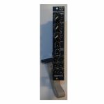
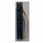
Doepfer A-105-2v 24dB Low Pass (SSI-Type) Filter Vintage Edition Module (black) (filter/oscillator synth module)
Cat: 973745 Rel: 14 Nov 23 • View all Synth modules
24dB SSI low pass filter module - 4HP.
Notes: Module A-105-2V is a voltage controlled low pass filter with 24dB/octave slope.
It is the successor of the A-105 which had to be discontinued because the obsolete SSM2044 filter circuit. The A-105-2 is based on the SSI2144 which is in turn the successor circuit of the SSM2044. The features of both modules are nearly the same. The main difference is the clearly reduced front panel width of the A-105-2 (4HP instead of 8HP) and the associated changes of the controls and sockets positions. In addition the A-105-2 is equipped with 2 audio inputs.
The module has these controls and in/outputs available:
Control Frequ: manual frequency control
Control FCV2: attenuator for the frequency control voltage applied to socket FCV2
Control Q: manual resonance control
Control QCV: attenuator for the resonance control voltage applied to socket QCV
Control Input 1 Level: attenuator for the audio input signal applied to socket Input 1
Socket Input 1: audio input 1 (with attenuator)
Socket Input 2: audio input 2 (without attenuator)
Socket FCV1: frequency control voltage 1 (without attenuator, about 1V/oct scale)
Socket FCV2: frequency control voltage 2 (with attenuator)
Socket QCV: resonance control voltage (with attenuator)
Socket Out: audio output
Technical notes:
Frequency range: about 15Hz ... 15 kHz
Resonance up to self oscillation
Max. input voltage at Input 2 without clipping/distortion: about 15Vpp
Max. output voltage without clipping/distortion: about 15Vpp
The signals of both inputs are mixed before they are processed by the filter. This saves an external mixer for small setups.
Depth: 45 mm
HP : 4
… Read moreIt is the successor of the A-105 which had to be discontinued because the obsolete SSM2044 filter circuit. The A-105-2 is based on the SSI2144 which is in turn the successor circuit of the SSM2044. The features of both modules are nearly the same. The main difference is the clearly reduced front panel width of the A-105-2 (4HP instead of 8HP) and the associated changes of the controls and sockets positions. In addition the A-105-2 is equipped with 2 audio inputs.
The module has these controls and in/outputs available:
Control Frequ: manual frequency control
Control FCV2: attenuator for the frequency control voltage applied to socket FCV2
Control Q: manual resonance control
Control QCV: attenuator for the resonance control voltage applied to socket QCV
Control Input 1 Level: attenuator for the audio input signal applied to socket Input 1
Socket Input 1: audio input 1 (with attenuator)
Socket Input 2: audio input 2 (without attenuator)
Socket FCV1: frequency control voltage 1 (without attenuator, about 1V/oct scale)
Socket FCV2: frequency control voltage 2 (with attenuator)
Socket QCV: resonance control voltage (with attenuator)
Socket Out: audio output
Technical notes:
Frequency range: about 15Hz ... 15 kHz
Resonance up to self oscillation
Max. input voltage at Input 2 without clipping/distortion: about 15Vpp
Max. output voltage without clipping/distortion: about 15Vpp
The signals of both inputs are mixed before they are processed by the filter. This saves an external mixer for small setups.
Depth: 45 mm
HP : 4
1 in stock $124.42
Click for better price!
or call +44 20 7424 1960
quote 973745
quote 973745
People also bought...
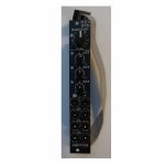
Doepfer A-130-2v VCAs Dual Linear/Exponential VCA Slim Line Series Vintage Edition Module (black) (dual/stereo/VCA synth module)
Cat: 973749 Rel: 14 Nov 23 • View all Synth modules
Dual linear/exponential VCA module - 4HP.
Notes: Module A-130-2v is composed of two identical voltage controlled amplifiers (VCA). Each VCA has a manual gain control (also named Initial Gain) and a control voltage input with attenuator. The character of the control scale can be switched to linear or exponential. All inputs and outputs are DC coupled. Consequently the VCAs can be used to process both audio and control voltages (e.g. for voltage control of the level of LFO or envelope signals). The signal input has no attenuator available but is capable to process up to 16Vpp signals (i.e. -8V...+8V) without distortion. For the processing of higher levels an external attenuator (e.g. A-183-1) is recommended.
The amplification range is 0...1. Even with a higher external control voltage the amplification remains at 1 (kind of "amplification clipping" at 1).
Controls (for each of both units):
Gain: manual gain control (Initial Gain) in the range 0...1
CV: attenuator for the CV input
lin/exp: switches the VCA characteristic to linear or exponential, in center position the VCA is off (mute function)
Inputs and outputs (for each of both units):
CV: control voltage input, min. +5V required for max. amplification (1) with CV control fully CW and Gain fully CCW
In: signal input, max. 16Vpp (+8V...-8V) without distortion
Out: signal output
A-130-2v is the slim version of module A-132-3 and offers essentially the same features. But the distances between the controls are smaller and rubberized small-sized knobs are used. In return the front panel has 4 HP only which is half the width of the A-132-3. The module is primarily planned for applications where only limited space is available.
Power consumption: 30mA at +12V and 30mA at -12V
Depth: 50mm
HP : 4
… Read moreThe amplification range is 0...1. Even with a higher external control voltage the amplification remains at 1 (kind of "amplification clipping" at 1).
Controls (for each of both units):
Gain: manual gain control (Initial Gain) in the range 0...1
CV: attenuator for the CV input
lin/exp: switches the VCA characteristic to linear or exponential, in center position the VCA is off (mute function)
Inputs and outputs (for each of both units):
CV: control voltage input, min. +5V required for max. amplification (1) with CV control fully CW and Gain fully CCW
In: signal input, max. 16Vpp (+8V...-8V) without distortion
Out: signal output
A-130-2v is the slim version of module A-132-3 and offers essentially the same features. But the distances between the controls are smaller and rubberized small-sized knobs are used. In return the front panel has 4 HP only which is half the width of the A-132-3. The module is primarily planned for applications where only limited space is available.
Power consumption: 30mA at +12V and 30mA at -12V
Depth: 50mm
HP : 4
2 in stock $94.36
Click for better price!
or call +44 20 7424 1960
quote 973749
quote 973749
People also bought...
Doepfer A-147-5v Quad VCLFO Vintage Edition Module (black) (LFO synth module)
Cat: 973760 Rel: 14 Nov 23 • View all Synth modules
Quad VCLFO module - 4HP.
Notes: Module A-147-5v contains four voltage controlled low frequency oscillators (VCLFO) with triangle waveform outputs. All LFOs share a common frequency control. Each of the LFOs 2, 3 features a Delta control which is used to shift the frequency of the LFO in question up or down. With the Delta controls at center positions the frequencies of all LFOs are roughly the same. To control the frequencies by external control voltages four CV inputs are available which follow roughly the 1V/oct standard.
The module has these controls and in/outputs available:
Control F: manual control of the frequency for all four LFOs
Control Delta F2, F3 and F4: manual control of the frequency shift up/down for the LFO in question
Sockets CV 1...4: Frequency control voltage inputs (normalled from top to bottom)
Sockets with triangle symbol 1...4: triangle outputs
LEDs: visual displays of the triangle outputs (red = positive, yellow = negative output voltage)
Application examples:
Generation of four triangle modulation signals with a common frequency control for all LFOs and individual controls for the frequency deviation of each LFO, manually adjustable and controllable by external control voltages
Generation of modulation signals for polyphonic FM/PWM applications. For this the four CV inputs are connected to the same control voltages which are used to control the frequencies of the corresponding VCOs. That way each LFO follows the frequency of the associated VCO with the possibility to control the frequency of all VCOs (control F) and the frequency deviations (Delta F controls). For the simultaneous modulation depth control the Quad VCA module A-130-4 is recommended.
Generation of complex modulation signals by summing up the outputs (e.g. by means of a mixer module A-138n / A-138i / A-138j)
Technical notes:
The level of the triangle outputs is about +/-5V (10Vpp)
The manually adjustable frequency ranges from about 0.025 Hz (about 40 seconds) to about 50 Hz with the delta controls of LFOs 2, 3 and 4 about center position
The frequency deviations adjusted by the delta controls are about +/-1:5. Example: with 1 Hz in center position the frequency shift ranges from about 0.2 Hz in position -5 to about 5 Hz in position +5 (1 Hz/5 = 0.2 Hz, 1 Hz*5 = 5 Hz).
The manual frequency controls and the control voltage inputs have an exponential control behavior
With external control voltage the max. frequency is about 150 Hz, the minimum frequency
The scale of the CV inputs is roughly 1V/oct (not adjustable)
The CV inputs are normalled from top to bottom. Provided that only socket CV1 is patched CV1 controls the frequencies of all four LFOs.
When each CV input is patched to it's own control voltage each LFO is controlled individually by it's own CV. In this case CV1 controls only the frequency of LFO1.
Internally the rectangle outputs are available at four terminals (typ level +/-10V or 20Vpp). If required they can be wired to four sockets of a DIY breakout module made by the user, 1k protection resistors are recommended to avoid short circuits. If lower levels are required passive attenuators (voltage dividers) may be used.
Internally is even an (unbufferd) triangle sum signal available. For this each of the four triangle outputs is simply connected to the sum output terminal via a 47k resistor. This output has high impedance and should be buffered or amplified to avoid level drop when the load changes (e.g. by means of an A-180-3 or A-180-4 or A-183-3).
By changing the values of the capacitors in the LFO circuits even other frequency ranges are possible (e.g. Quad VCO to form kind of a cloud VCO). Pay attention that the accuracy of the CV input scales is not sufficient for precise 1V/oct VCO applications. The 1V/Oct scales cannot be adjusted and the circuits are not temperature compensated.
Dimensions
4 HP
45 mm deep
… Read moreThe module has these controls and in/outputs available:
Control F: manual control of the frequency for all four LFOs
Control Delta F2, F3 and F4: manual control of the frequency shift up/down for the LFO in question
Sockets CV 1...4: Frequency control voltage inputs (normalled from top to bottom)
Sockets with triangle symbol 1...4: triangle outputs
LEDs: visual displays of the triangle outputs (red = positive, yellow = negative output voltage)
Application examples:
Generation of four triangle modulation signals with a common frequency control for all LFOs and individual controls for the frequency deviation of each LFO, manually adjustable and controllable by external control voltages
Generation of modulation signals for polyphonic FM/PWM applications. For this the four CV inputs are connected to the same control voltages which are used to control the frequencies of the corresponding VCOs. That way each LFO follows the frequency of the associated VCO with the possibility to control the frequency of all VCOs (control F) and the frequency deviations (Delta F controls). For the simultaneous modulation depth control the Quad VCA module A-130-4 is recommended.
Generation of complex modulation signals by summing up the outputs (e.g. by means of a mixer module A-138n / A-138i / A-138j)
Technical notes:
The level of the triangle outputs is about +/-5V (10Vpp)
The manually adjustable frequency ranges from about 0.025 Hz (about 40 seconds) to about 50 Hz with the delta controls of LFOs 2, 3 and 4 about center position
The frequency deviations adjusted by the delta controls are about +/-1:5. Example: with 1 Hz in center position the frequency shift ranges from about 0.2 Hz in position -5 to about 5 Hz in position +5 (1 Hz/5 = 0.2 Hz, 1 Hz*5 = 5 Hz).
The manual frequency controls and the control voltage inputs have an exponential control behavior
With external control voltage the max. frequency is about 150 Hz, the minimum frequency
The scale of the CV inputs is roughly 1V/oct (not adjustable)
The CV inputs are normalled from top to bottom. Provided that only socket CV1 is patched CV1 controls the frequencies of all four LFOs.
When each CV input is patched to it's own control voltage each LFO is controlled individually by it's own CV. In this case CV1 controls only the frequency of LFO1.
Internally the rectangle outputs are available at four terminals (typ level +/-10V or 20Vpp). If required they can be wired to four sockets of a DIY breakout module made by the user, 1k protection resistors are recommended to avoid short circuits. If lower levels are required passive attenuators (voltage dividers) may be used.
Internally is even an (unbufferd) triangle sum signal available. For this each of the four triangle outputs is simply connected to the sum output terminal via a 47k resistor. This output has high impedance and should be buffered or amplified to avoid level drop when the load changes (e.g. by means of an A-180-3 or A-180-4 or A-183-3).
By changing the values of the capacitors in the LFO circuits even other frequency ranges are possible (e.g. Quad VCO to form kind of a cloud VCO). Pay attention that the accuracy of the CV input scales is not sufficient for precise 1V/oct VCO applications. The 1V/Oct scales cannot be adjusted and the circuits are not temperature compensated.
Dimensions
4 HP
45 mm deep
out of stock $111.97
People also bought...
Doepfer A-105-2 24dB Low Pass (SSI-Type) Filter Module (silver) (filter/oscillator synth module)
Cat: 973741 Rel: 14 Nov 23 • View all Synth modules
24dB SSI low pass filter - 4HP.
Notes: Module A-105-2 is a voltage controlled low pass filter with 24dB/octave slope.
It is the successor of the A-105 which had to be discontinued because the obsolete SSM2044 filter circuit. The A-105-2 is based on the SSI2144 which is in turn the successor circuit of the SSM2044. The features of both modules are nearly the same. The main difference is the clearly reduced front panel width of the A-105-2 (4HP instead of 8HP) and the associated changes of the controls and sockets positions. In addition the A-105-2 is equipped with 2 audio inputs.
The module has these controls and in/outputs available:
Control Frequ: manual frequency control
Control FCV2: attenuator for the frequency control voltage applied to socket FCV2
Control Q: manual resonance control
Control QCV: attenuator for the resonance control voltage applied to socket QCV
Control Input 1 Level: attenuator for the audio input signal applied to socket Input 1
Socket Input 1: audio input 1 (with attenuator)
Socket Input 2: audio input 2 (without attenuator)
Socket FCV1: frequency control voltage 1 (without attenuator, about 1V/oct scale)
Socket FCV2: frequency control voltage 2 (with attenuator)
Socket QCV: resonance control voltage (with attenuator)
Socket Out: audio output
Technical notes:
Frequency range: about 15Hz ... 15 kHz
Resonance up to self oscillation
Max. input voltage at Input 2 without clipping/distortion: about 15Vpp
Max. output voltage without clipping/distortion: about 15Vpp
The signals of both inputs are mixed before they are processed by the filter. This saves an external mixer for small setups.
Depth: 45 mm
HP : 4
… Read moreIt is the successor of the A-105 which had to be discontinued because the obsolete SSM2044 filter circuit. The A-105-2 is based on the SSI2144 which is in turn the successor circuit of the SSM2044. The features of both modules are nearly the same. The main difference is the clearly reduced front panel width of the A-105-2 (4HP instead of 8HP) and the associated changes of the controls and sockets positions. In addition the A-105-2 is equipped with 2 audio inputs.
The module has these controls and in/outputs available:
Control Frequ: manual frequency control
Control FCV2: attenuator for the frequency control voltage applied to socket FCV2
Control Q: manual resonance control
Control QCV: attenuator for the resonance control voltage applied to socket QCV
Control Input 1 Level: attenuator for the audio input signal applied to socket Input 1
Socket Input 1: audio input 1 (with attenuator)
Socket Input 2: audio input 2 (without attenuator)
Socket FCV1: frequency control voltage 1 (without attenuator, about 1V/oct scale)
Socket FCV2: frequency control voltage 2 (with attenuator)
Socket QCV: resonance control voltage (with attenuator)
Socket Out: audio output
Technical notes:
Frequency range: about 15Hz ... 15 kHz
Resonance up to self oscillation
Max. input voltage at Input 2 without clipping/distortion: about 15Vpp
Max. output voltage without clipping/distortion: about 15Vpp
The signals of both inputs are mixed before they are processed by the filter. This saves an external mixer for small setups.
Depth: 45 mm
HP : 4
2 in stock $103.69
People also bought...
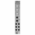
Doepfer A-130-4 Quad VCA Module (VCA synth module)
Cat: 973752 Rel: 14 Nov 23 • View all Synth modules
Quad VCA module - 4HP.
Notes: Module A-130-4 contains four linear VCAs with a common level control section for all four VCAs. It can be used for all applications of simultaneous amplitude/level control of up to four different audio or CV signals. A-130-4 is the replacement of the no longer available module A-132-2. Compared to the A-132-2 the width has been reduced from 8HP to 4HP.
The module has these controls and in/outputs available:
Control Man.: manual control of the amplification
Control CV: attenuator for the control voltage applied to socket CVo socket Input 1
Sockets In 1...4: VCA inputs 1...4
Sockets Out 1...4: VCA outputs 1...4
Application examples:
simultaneous amplitude/level control of up to four different audio or CV signals
polyphonic application 1: simultaneous control of the frequency modulation depth of 4 VCOs (Quad-LFO A-145-4 or Quad-VCLFO A-147-5 > A-130-4 > FM inputs A-111-4)
polyphonic application 2: simultaneous control of the pulsewidth modulation depth of 4 VCOs (Quad-LFO A-145-4 or Quad-VCLFO A-147-5 > A-130-4 > PWM inputs A-111-4)
simultaneous control of quadrophonic signals
Technical notes:
The maximum amplification for each VCA is about 1 ("Man." control fully CW). Even with an external control voltage applied to the CV input the maximum amplification is limited to 1.
The module is equipped with two internal connectors (pin headers with 4 pins each). Pin header #1 can be used to normalize the four inputs to other modules (e.g. Quad LFO A-145-4 or A-147-5, Quad ADSR A-143-2). Pin header #2 can be used to connect the four outputs to other modules.
The max. level at the VCA inputs without clipping/distortion is about 20Vpp or +/-10V.
Dimensions
4 HP
45 mm deep
… Read moreThe module has these controls and in/outputs available:
Control Man.: manual control of the amplification
Control CV: attenuator for the control voltage applied to socket CVo socket Input 1
Sockets In 1...4: VCA inputs 1...4
Sockets Out 1...4: VCA outputs 1...4
Application examples:
simultaneous amplitude/level control of up to four different audio or CV signals
polyphonic application 1: simultaneous control of the frequency modulation depth of 4 VCOs (Quad-LFO A-145-4 or Quad-VCLFO A-147-5 > A-130-4 > FM inputs A-111-4)
polyphonic application 2: simultaneous control of the pulsewidth modulation depth of 4 VCOs (Quad-LFO A-145-4 or Quad-VCLFO A-147-5 > A-130-4 > PWM inputs A-111-4)
simultaneous control of quadrophonic signals
Technical notes:
The maximum amplification for each VCA is about 1 ("Man." control fully CW). Even with an external control voltage applied to the CV input the maximum amplification is limited to 1.
The module is equipped with two internal connectors (pin headers with 4 pins each). Pin header #1 can be used to normalize the four inputs to other modules (e.g. Quad LFO A-145-4 or A-147-5, Quad ADSR A-143-2). Pin header #2 can be used to connect the four outputs to other modules.
The max. level at the VCA inputs without clipping/distortion is about 20Vpp or +/-10V.
Dimensions
4 HP
45 mm deep
1 in stock $79.83
People also bought...
Doepfer A-147-5 Quad VCLFO Module (silver) (LFO synth module)
Cat: 973756 Rel: 14 Nov 23 • View all Synth modules
Quad VCLFO module - 4HP.
Notes: Module A-147-5 contains four voltage controlled low frequency oscillators (VCLFO) with triangle waveform outputs. All LFOs share a common frequency control. Each of the LFOs 2, 3 features a Delta control which is used to shift the frequency of the LFO in question up or down. With the Delta controls at center positions the frequencies of all LFOs are roughly the same. To control the frequencies by external control voltages four CV inputs are available which follow roughly the 1V/oct standard.
The module has these controls and in/outputs available:
Control F: manual control of the frequency for all four LFOs
Control Delta F2, F3 and F4: manual control of the frequency shift up/down for the LFO in question
Sockets CV 1...4: Frequency control voltage inputs (normalled from top to bottom)
Sockets with triangle symbol 1...4: triangle outputs
LEDs: visual displays of the triangle outputs (red = positive, yellow = negative output voltage)
Application examples:
Generation of four triangle modulation signals with a common frequency control for all LFOs and individual controls for the frequency deviation of each LFO, manually adjustable and controllable by external control voltages
Generation of modulation signals for polyphonic FM/PWM applications. For this the four CV inputs are connected to the same control voltages which are used to control the frequencies of the corresponding VCOs. That way each LFO follows the frequency of the associated VCO with the possibility to control the frequency of all VCOs (control F) and the frequency deviations (Delta F controls). For the simultaneous modulation depth control the Quad VCA module A-130-4 is recommended.
Generation of complex modulation signals by summing up the outputs (e.g. by means of a mixer module A-138n / A-138i / A-138j)
Technical notes:
The level of the triangle outputs is about +/-5V (10Vpp)
The manually adjustable frequency ranges from about 0.025 Hz (about 40 seconds) to about 50 Hz with the delta controls of LFOs 2, 3 and 4 about center position
The frequency deviations adjusted by the delta controls are about +/-1:5. Example: with 1 Hz in center position the frequency shift ranges from about 0.2 Hz in position -5 to about 5 Hz in position +5 (1 Hz/5 = 0.2 Hz, 1 Hz*5 = 5 Hz).
The manual frequency controls and the control voltage inputs have an exponential control behavior
With external control voltage the max. frequency is about 150 Hz, the minimum frequency
The scale of the CV inputs is roughly 1V/oct (not adjustable)
The CV inputs are normalled from top to bottom. Provided that only socket CV1 is patched CV1 controls the frequencies of all four LFOs.
When each CV input is patched to it's own control voltage each LFO is controlled individually by it's own CV. In this case CV1 controls only the frequency of LFO1.
Internally the rectangle outputs are available at four terminals (typ level +/-10V or 20Vpp). If required they can be wired to four sockets of a DIY breakout module made by the user, 1k protection resistors are recommended to avoid short circuits. If lower levels are required passive attenuators (voltage dividers) may be used.
Internally is even an (unbufferd) triangle sum signal available. For this each of the four triangle outputs is simply connected to the sum output terminal via a 47k resistor. This output has high impedance and should be buffered or amplified to avoid level drop when the load changes (e.g. by means of an A-180-3 or A-180-4 or A-183-3).
By changing the values of the capacitors in the LFO circuits even other frequency ranges are possible (e.g. Quad VCO to form kind of a cloud VCO). Pay attention that the accuracy of the CV input scales is not sufficient for precise 1V/oct VCO applications. The 1V/Oct scales cannot be adjusted and the circuits are not temperature compensated.
Dimensions
4 HP
45 mm deep
… Read moreThe module has these controls and in/outputs available:
Control F: manual control of the frequency for all four LFOs
Control Delta F2, F3 and F4: manual control of the frequency shift up/down for the LFO in question
Sockets CV 1...4: Frequency control voltage inputs (normalled from top to bottom)
Sockets with triangle symbol 1...4: triangle outputs
LEDs: visual displays of the triangle outputs (red = positive, yellow = negative output voltage)
Application examples:
Generation of four triangle modulation signals with a common frequency control for all LFOs and individual controls for the frequency deviation of each LFO, manually adjustable and controllable by external control voltages
Generation of modulation signals for polyphonic FM/PWM applications. For this the four CV inputs are connected to the same control voltages which are used to control the frequencies of the corresponding VCOs. That way each LFO follows the frequency of the associated VCO with the possibility to control the frequency of all VCOs (control F) and the frequency deviations (Delta F controls). For the simultaneous modulation depth control the Quad VCA module A-130-4 is recommended.
Generation of complex modulation signals by summing up the outputs (e.g. by means of a mixer module A-138n / A-138i / A-138j)
Technical notes:
The level of the triangle outputs is about +/-5V (10Vpp)
The manually adjustable frequency ranges from about 0.025 Hz (about 40 seconds) to about 50 Hz with the delta controls of LFOs 2, 3 and 4 about center position
The frequency deviations adjusted by the delta controls are about +/-1:5. Example: with 1 Hz in center position the frequency shift ranges from about 0.2 Hz in position -5 to about 5 Hz in position +5 (1 Hz/5 = 0.2 Hz, 1 Hz*5 = 5 Hz).
The manual frequency controls and the control voltage inputs have an exponential control behavior
With external control voltage the max. frequency is about 150 Hz, the minimum frequency
The scale of the CV inputs is roughly 1V/oct (not adjustable)
The CV inputs are normalled from top to bottom. Provided that only socket CV1 is patched CV1 controls the frequencies of all four LFOs.
When each CV input is patched to it's own control voltage each LFO is controlled individually by it's own CV. In this case CV1 controls only the frequency of LFO1.
Internally the rectangle outputs are available at four terminals (typ level +/-10V or 20Vpp). If required they can be wired to four sockets of a DIY breakout module made by the user, 1k protection resistors are recommended to avoid short circuits. If lower levels are required passive attenuators (voltage dividers) may be used.
Internally is even an (unbufferd) triangle sum signal available. For this each of the four triangle outputs is simply connected to the sum output terminal via a 47k resistor. This output has high impedance and should be buffered or amplified to avoid level drop when the load changes (e.g. by means of an A-180-3 or A-180-4 or A-183-3).
By changing the values of the capacitors in the LFO circuits even other frequency ranges are possible (e.g. Quad VCO to form kind of a cloud VCO). Pay attention that the accuracy of the CV input scales is not sufficient for precise 1V/oct VCO applications. The 1V/Oct scales cannot be adjusted and the circuits are not temperature compensated.
Dimensions
4 HP
45 mm deep
1 in stock $98.50
People also bought...
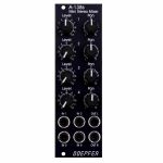
Doepfer A-138sv Mini Stereo Mixer Vintage Edition Module (black) (B-STOCK) (dual/stereo/mixer/panning/quad synth module)
Cat: 980376 Rel: 01 Jan 90 • View all Synth modules
B-STOCK: Item refurbished, repaired and in perfect working order.
Notes: ***B-STOCK: Item refurbished, repaired and in perfect working order.***
A-138s is a simple but useful 4-in-2 mixing tool. It has four inputs available. Each input is equipped with an attenuator (Level) and a panning control that is used to distribute the signal to the left and right output. Beyond stereo mixing it is equally suited to create variable parallel routings. For example: Any of the four inputs may be routed in variable intensity to feed two filters.
You may regard the A-138s as a smaller version of the A-138m Matrix Mixer.
Inputs and outputs are DC coupled, i.e. the module can be used for the mixing of control signals too.
- 3U Eurorack module, 8 HP wide, 30 mm in depth
- Power consumption: 10 mA at +12 V and 10 mA at -12 V
… Read moreA-138s is a simple but useful 4-in-2 mixing tool. It has four inputs available. Each input is equipped with an attenuator (Level) and a panning control that is used to distribute the signal to the left and right output. Beyond stereo mixing it is equally suited to create variable parallel routings. For example: Any of the four inputs may be routed in variable intensity to feed two filters.
You may regard the A-138s as a smaller version of the A-138m Matrix Mixer.
Inputs and outputs are DC coupled, i.e. the module can be used for the mixing of control signals too.
- 3U Eurorack module, 8 HP wide, 30 mm in depth
- Power consumption: 10 mA at +12 V and 10 mA at -12 V
1 in stock $77.63
People also bought...
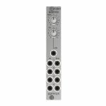
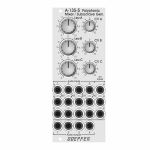
Doepfer A-135-5 Polyphonic Voltage Controlled Mixer/Suboctave Generator Module (mixer synth module)
Cat: 945421 Rel: 19 Oct 23 • View all Synth modules
Polyphonic voltage controlled mixer & suboctave generator module - 10HP.
Notes: Module A-135-5 is a combination of a voltage controlled polyphonic mixer and a polyphonic suboctave generator. It is made of 12 voltage controlled amplifiers (VCAs) which are arranged in form of a 4x3 matrix. Herewith up to three four-voice polyphonic signals (e.g. the outputs of three polyphonic VCOs A-111-4) can be mixed. The level of each of the three polyphonic channels (A, B, C) with four voices each can be controlled manually or by means of an external control voltage with associated attenuators.
In addition the module features four frequency dividers which derive the suboctaves from the four input signals of channel A. The suboctave signals are wired to the switching contacts of the sockets of channel B. As long as the sockets of channel B are not patched the suboctave signals of channel A are used as inputs for channel B. The suboctaves are symmetrical rectangle waves with half the frequency of the corresponding signal A. For example two polyphonic VCOs A-111-4) can be used and patched to the channels A and C. Channel B then provides the suboctaves of channel A.
As the module is fully DC coupled it can be used also for the mixing of control voltages in a polyphonic environment (e.g. for envelopes, LFOs or other control voltages).
The switching contacts of the 12 input sockets and the four outputs are internally connected to pin headers. That way the module can be internally pre-patched to other polyphonic modules (e.g. the four inputs A to an A-111-4, the four inputs C to another A-111-4 and the outputs to the polyphonic filter A-105-4). As the switching contacts of the sockets are used for the internal pre-patching the internal patch can be overridden by using the sockets at the front panel.
The module has these controls and in/outputs available:
Controls Lev.A, Lev.B, Lev.C: manual level adjustment of the channels A, B and C
Controls CV A, CV B, CV C: attenuators for the corresponding control voltage inputs
Sockets A1...4: inputs channel A
Sockets B1...4: inputs channel B (if the sockets are not patched the suboctave signals are used for the inputs B)
Sockets C1...4: inputs channel C
Sockets CV A. CV B, CV C: control voltage inputs for the channels A, B and C
Sockets Out 1...4: outputs
Dimensions
10 HP
55 mm deep
… Read moreIn addition the module features four frequency dividers which derive the suboctaves from the four input signals of channel A. The suboctave signals are wired to the switching contacts of the sockets of channel B. As long as the sockets of channel B are not patched the suboctave signals of channel A are used as inputs for channel B. The suboctaves are symmetrical rectangle waves with half the frequency of the corresponding signal A. For example two polyphonic VCOs A-111-4) can be used and patched to the channels A and C. Channel B then provides the suboctaves of channel A.
As the module is fully DC coupled it can be used also for the mixing of control voltages in a polyphonic environment (e.g. for envelopes, LFOs or other control voltages).
The switching contacts of the 12 input sockets and the four outputs are internally connected to pin headers. That way the module can be internally pre-patched to other polyphonic modules (e.g. the four inputs A to an A-111-4, the four inputs C to another A-111-4 and the outputs to the polyphonic filter A-105-4). As the switching contacts of the sockets are used for the internal pre-patching the internal patch can be overridden by using the sockets at the front panel.
The module has these controls and in/outputs available:
Controls Lev.A, Lev.B, Lev.C: manual level adjustment of the channels A, B and C
Controls CV A, CV B, CV C: attenuators for the corresponding control voltage inputs
Sockets A1...4: inputs channel A
Sockets B1...4: inputs channel B (if the sockets are not patched the suboctave signals are used for the inputs B)
Sockets C1...4: inputs channel C
Sockets CV A. CV B, CV C: control voltage inputs for the channels A, B and C
Sockets Out 1...4: outputs
Dimensions
10 HP
55 mm deep
out of stock $149.30

People also bought...
Doepfer A-111-6v Miniature Synthesiser Voice Vintage Edition Module (black) (B-STOCK) (synth voice synth module)
Cat: 970408 Rel: 01 Jan 90 • View all Synth modules
B-STOCK: Slight dent om the edge, otherwise in perfect condition
Notes: ***B-STOCK: Slight dent om the edge, otherwise in perfect condition***
VCO:
- Tune: manual tune control (with an internal jumper the range can be set to ~ +/-1 half an octave or ~ +/-2.5 octaves)
- Oct: range switch -1 / 0 / +1 octave
- Mod: modulation depth (attenuator wired to the Mod. socket)
- Dest: switch that is used to address the modulation to frequency modulation (position FM) or pulsewidth modulation (positon PM), in centre positon no modulation
- PW: manual pulsewidth control for rectangle waveform, PW can be also modulated by the Mod. input as mentioned above
- Wave: waveform switch (sawtooth / off / triangle), the sum of the waveform chosen by this switch and the rectangle is fed into the VCF (to turn the rectangle off the PW control has to be set fully CCW or fully CW)
- 1V/Oct. (socket): external CV input for VCO frequency (1V/octave)
- Access to internal bus CV (via jumper, optional, please remove the bus jumper if this feature is not used to avoid unwanted frequency modulation as then the unused CV line of the bus works as a kind of antenna)
- Triangle core VCO, frequency range about 32Hz ... 8kHz
Balance unit:
- The balance unit is made of two VCAs which are controlled by the sum of manual Balance control and the balance CV input in the opposite direction.
- The audio input of VCA1 is hard-wired to the VCO output, audio input 2 is connected to the socket Ext.In.
- The output of the balance unit is used as audio input for the VCF
- Bal.: manual balance control, fully CCW the internal VCO is used, fully CW the external signal (Ext.In) is used, at centre position both signals have about the same level
- CV Bal.: CV input for balance (range about 0...+5V)
- Ext. In: external audio input for VCA2, about 5 Vpp level required for similar loudness as the internal VCO
- This socket is normalled to the internal VCO suboctave f/2 signal (rectangle with half the frequency), if no external signal is applied the suboctave signal is used as the second signal for the balance unit
VCF:
- 24 dB low pass
- Frq: manual frequency control
- FM1: frequency modulation depth (attenuator wired to the VCF FM1 socket, the socket is normalled to the internal Envelope signal and then FM1 controls the modulation depth of the internal envelope applied to the filter)
- FM2 (socket) : second CV input for VCF without attenuator (about 1V/octave), can be used e.g. for VCF tracking by connecting the same CV which is used also for the VCO frequency
- Res: manual resonance control (up to self oscillation)
- If the VCO is turned off (waveform switch = centre position, pulsewidth control = fully CCW or CW) and the VCF resonance is set to maximum the module can be used as a sine oscillator, the tracking at socket VCF FM2 is about 1V/octave (not as precise as the VCO but much better than most other filters)
- ~ 11 octaves frequency range (~ 10 Hz ... 20kHz)
VCA:
- Gain: manual amplitude control (initial gain), can be used to open the VCA without envelope signal
- VCA (switch): used to switch between gate and envelope as control signal for the VCA, in centre position the VCA is not controlled by envelope or gate
- Note: when gate is used the VCA is controlled directly by the gate signal (i.e. hard on/off), this may lead to clicking noise under certain conditions (especially with low VCO/VCF frequencies)
- Special control scale: exponential scale in the range from about -20dB to -80/90dB, linear scale from about -20dB to 0dB
- Remark: this special control scale results in a loudness behaviour that is a bit different from pure linear or exponential VCAs
- Out: audio output of the module (= VCA output)
Envelope:
- Gate (socket): Gate input (min. +5V), can be normalled to the bus gate signal by means of a jumper
- Att: manual control for Attack
- D/R: manual control for Decay/Release
- Env. (switch): used to switch between A/D, ADSR and A/R mode of the envelope generator, in centre position (ADSR) the sustain level is fixed to about 50%
- Envelope (socket): envelope output (about +10V)
- CVT (socket): CV input for time control, by means of two internal jumpers one can select which time parameters are controlled by the CVT input (e.g. A only or D/R only or A/D/R) and in which direction (i.e. if an increasing CVT shortens or stretches the time parameter in question)
- Envelope LED display
- Attack time range: ~ 1ms ... 5 sec (can be extended by using the CVT input)
- Decay/Release time range: ~ 1ms ... 15 sec (can be extended by using the CVT input)
… Read moreVCO:
- Tune: manual tune control (with an internal jumper the range can be set to ~ +/-1 half an octave or ~ +/-2.5 octaves)
- Oct: range switch -1 / 0 / +1 octave
- Mod: modulation depth (attenuator wired to the Mod. socket)
- Dest: switch that is used to address the modulation to frequency modulation (position FM) or pulsewidth modulation (positon PM), in centre positon no modulation
- PW: manual pulsewidth control for rectangle waveform, PW can be also modulated by the Mod. input as mentioned above
- Wave: waveform switch (sawtooth / off / triangle), the sum of the waveform chosen by this switch and the rectangle is fed into the VCF (to turn the rectangle off the PW control has to be set fully CCW or fully CW)
- 1V/Oct. (socket): external CV input for VCO frequency (1V/octave)
- Access to internal bus CV (via jumper, optional, please remove the bus jumper if this feature is not used to avoid unwanted frequency modulation as then the unused CV line of the bus works as a kind of antenna)
- Triangle core VCO, frequency range about 32Hz ... 8kHz
Balance unit:
- The balance unit is made of two VCAs which are controlled by the sum of manual Balance control and the balance CV input in the opposite direction.
- The audio input of VCA1 is hard-wired to the VCO output, audio input 2 is connected to the socket Ext.In.
- The output of the balance unit is used as audio input for the VCF
- Bal.: manual balance control, fully CCW the internal VCO is used, fully CW the external signal (Ext.In) is used, at centre position both signals have about the same level
- CV Bal.: CV input for balance (range about 0...+5V)
- Ext. In: external audio input for VCA2, about 5 Vpp level required for similar loudness as the internal VCO
- This socket is normalled to the internal VCO suboctave f/2 signal (rectangle with half the frequency), if no external signal is applied the suboctave signal is used as the second signal for the balance unit
VCF:
- 24 dB low pass
- Frq: manual frequency control
- FM1: frequency modulation depth (attenuator wired to the VCF FM1 socket, the socket is normalled to the internal Envelope signal and then FM1 controls the modulation depth of the internal envelope applied to the filter)
- FM2 (socket) : second CV input for VCF without attenuator (about 1V/octave), can be used e.g. for VCF tracking by connecting the same CV which is used also for the VCO frequency
- Res: manual resonance control (up to self oscillation)
- If the VCO is turned off (waveform switch = centre position, pulsewidth control = fully CCW or CW) and the VCF resonance is set to maximum the module can be used as a sine oscillator, the tracking at socket VCF FM2 is about 1V/octave (not as precise as the VCO but much better than most other filters)
- ~ 11 octaves frequency range (~ 10 Hz ... 20kHz)
VCA:
- Gain: manual amplitude control (initial gain), can be used to open the VCA without envelope signal
- VCA (switch): used to switch between gate and envelope as control signal for the VCA, in centre position the VCA is not controlled by envelope or gate
- Note: when gate is used the VCA is controlled directly by the gate signal (i.e. hard on/off), this may lead to clicking noise under certain conditions (especially with low VCO/VCF frequencies)
- Special control scale: exponential scale in the range from about -20dB to -80/90dB, linear scale from about -20dB to 0dB
- Remark: this special control scale results in a loudness behaviour that is a bit different from pure linear or exponential VCAs
- Out: audio output of the module (= VCA output)
Envelope:
- Gate (socket): Gate input (min. +5V), can be normalled to the bus gate signal by means of a jumper
- Att: manual control for Attack
- D/R: manual control for Decay/Release
- Env. (switch): used to switch between A/D, ADSR and A/R mode of the envelope generator, in centre position (ADSR) the sustain level is fixed to about 50%
- Envelope (socket): envelope output (about +10V)
- CVT (socket): CV input for time control, by means of two internal jumpers one can select which time parameters are controlled by the CVT input (e.g. A only or D/R only or A/D/R) and in which direction (i.e. if an increasing CVT shortens or stretches the time parameter in question)
- Envelope LED display
- Attack time range: ~ 1ms ... 5 sec (can be extended by using the CVT input)
- Decay/Release time range: ~ 1ms ... 15 sec (can be extended by using the CVT input)
1 in stock $164.87

People also bought...
Doepfer A-140 ADSR Envelope Generator Module (silver) (B-STOCK) (envelope generator synth module)
Cat: 968709 Rel: 01 Jan 90 • View all Synth modules
B-STOCK: Box damaged, product in perfect working order
Notes: ***B-STOCK: Box damaged, product in perfect working order***
Module A-140 is an envelope generator, and, since it puts out control voltages, counts as one of the modulation devices in a modular system. As soon as the gate input receives sufficient voltage, the ADSR generates a variable voltage, changing in time, called an envelope. This varying voltage is output in normal (positive) and inverted form, and can be used, eg. for voltage controlled modulation of a VCO, VCF, or VCA, or for processing other modules' inputs and outputs.
The shape of the envelope is governed by four parameters: Attack, Decay, Sustain and Release.
The envelope is started (triggered) by a gate signal either from the INT.GATE voltage on the system bus, or, if a signal is put into it, from the gate input socket.
The envelope can also be re-triggered, i.e. start from scratch again, each time a trigger signal is sensed at the Retrig. input socket, when the gate is still open.
Module A-140 has available a three-position toggle switch to select one of three time ranges. The envelope duration ranges from about 50us (microseconds) up to several minutes.
In combination with the Comparator module A-167 a free-running "ADSR-LFO" can be realized.
… Read moreModule A-140 is an envelope generator, and, since it puts out control voltages, counts as one of the modulation devices in a modular system. As soon as the gate input receives sufficient voltage, the ADSR generates a variable voltage, changing in time, called an envelope. This varying voltage is output in normal (positive) and inverted form, and can be used, eg. for voltage controlled modulation of a VCO, VCF, or VCA, or for processing other modules' inputs and outputs.
The shape of the envelope is governed by four parameters: Attack, Decay, Sustain and Release.
The envelope is started (triggered) by a gate signal either from the INT.GATE voltage on the system bus, or, if a signal is put into it, from the gate input socket.
The envelope can also be re-triggered, i.e. start from scratch again, each time a trigger signal is sensed at the Retrig. input socket, when the gate is still open.
Module A-140 has available a three-position toggle switch to select one of three time ranges. The envelope duration ranges from about 50us (microseconds) up to several minutes.
In combination with the Comparator module A-167 a free-running "ADSR-LFO" can be realized.
out of stock $69.47
People also bought...
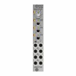
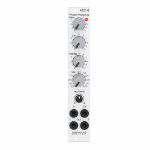
Doepfer A-101-8 Photo Phasing 8-Stage Phase Shifter Module (silver) (B-STOCK) (phase shifter/effect synth module)
Cat: 966281 Rel: 01 Jan 90 • View all Synth modules
B-STOCK: Box opened, but product is in excellent condition and in perfect working order
Notes: ***B-STOCK: Box opened, but product is in excellent condition and in perfect working order***
Module A-101-8 is a 8-stage phase shifter which uses light-sensitive resistors (LDR) and is a replica of the Compact Phasing A manufactured by the company Schulte in the seventies. The actual phasing circuit is identical to the historic model. Only the illumination control of the LDRs is different: the A-101-8 uses LEDs to illuminate the LDRs, the historic model used incandescent miniature lamps. And the A-101-8 has no built-in LFO but can be controlled by any external control voltage source (e.g. LFO, ADSR, random, Theremin, ribbon controller, sequencer, midi). The phasing offset (i.e. the base value for the phase shifting) and the modulation depth of the external control signal can be adjusted separately. The Compact Phasing A had no offset control but only a depth control for the built-in LFO. Feedback and mixing ratio of the output signal are set by two controls. The audio input is equipped with an attenuator. The module has two audio outputs available (same as the historic model) and a visual display of the phase shifting.
The module has these controls and in/outputs available:
Control Man. : manual control of the phase shift offset (base value)
Control CV: attenuator for the signal applied to the CV socket
Control Feedb.: Feedback or Resonance (similar function as filter resonance/feedback/emphasis)
Control Mix: sets the mixing ratio between original and phase shift signal appearing at output 1
fully CCW: only the modified input signal appears at output 1 (see note below *)
center: a mixture between the modified input signal and the phase shift signal appears at output 1, that's the standard position for the classical phasing effect
fully CW: the pure phase shifted signal appears at output 1 (e.g. for vibrato effects)
Control Input Level: attenuator for signal applied to the In socket
Socket In: audio input
Socket CV: control voltage input
Socket Out 1: audio output 1 (mix signal)
Socket Out 2: audio output 2 (modified input signal)
LED: visual control of the phase shift
The module has some peculiarities (same as the historic model):
The input signal is processed at first by a pre-stage which outputs a "modified" input signal (*). This signal is not processed by the phase shift stages but is affected by the feedback setting. Only when feedback is set to zero this signal is identical to the input signal. Otherwise it contains feedback components.
This signal is output on socket Out 2.
When both output sockets Out 1 and Out 2 are used as stereo channels one obtains a spatial stereo sound effect.
The same signals is also used for the CCW position of the mix control. With mix control fully CCW the unmodified signal appears only if the feedback control is set to zero. Otherwise it contains feedback components.
The historic model had two audio inputs: one 5-pin DIN socket and a 1/4" jack socket. The DIN socket was intended for high-level line signals. When the 1/4" jack socket was used the amplification of the pre-stage increased by about 100. The 1/4" jack socket was intended for low level signals (e.g. electric guitars or microphones). For this feature the A-101-8 has an internal jumper that can be used to increase the amplification. As long as the module is used within the A-100 system usually the lower amplification is used to avoid distortion.
The 8 photo resistors and LEDs are assembled within an small lighproof box. In addition the pc boards are made of lighproof black material to avoid interfering light from other modules or the bus board.
Dimensions
4 HP
45 mm deep
Current Draw
30 mA +12V
30 mA -12V
… Read moreModule A-101-8 is a 8-stage phase shifter which uses light-sensitive resistors (LDR) and is a replica of the Compact Phasing A manufactured by the company Schulte in the seventies. The actual phasing circuit is identical to the historic model. Only the illumination control of the LDRs is different: the A-101-8 uses LEDs to illuminate the LDRs, the historic model used incandescent miniature lamps. And the A-101-8 has no built-in LFO but can be controlled by any external control voltage source (e.g. LFO, ADSR, random, Theremin, ribbon controller, sequencer, midi). The phasing offset (i.e. the base value for the phase shifting) and the modulation depth of the external control signal can be adjusted separately. The Compact Phasing A had no offset control but only a depth control for the built-in LFO. Feedback and mixing ratio of the output signal are set by two controls. The audio input is equipped with an attenuator. The module has two audio outputs available (same as the historic model) and a visual display of the phase shifting.
The module has these controls and in/outputs available:
Control Man. : manual control of the phase shift offset (base value)
Control CV: attenuator for the signal applied to the CV socket
Control Feedb.: Feedback or Resonance (similar function as filter resonance/feedback/emphasis)
Control Mix: sets the mixing ratio between original and phase shift signal appearing at output 1
fully CCW: only the modified input signal appears at output 1 (see note below *)
center: a mixture between the modified input signal and the phase shift signal appears at output 1, that's the standard position for the classical phasing effect
fully CW: the pure phase shifted signal appears at output 1 (e.g. for vibrato effects)
Control Input Level: attenuator for signal applied to the In socket
Socket In: audio input
Socket CV: control voltage input
Socket Out 1: audio output 1 (mix signal)
Socket Out 2: audio output 2 (modified input signal)
LED: visual control of the phase shift
The module has some peculiarities (same as the historic model):
The input signal is processed at first by a pre-stage which outputs a "modified" input signal (*). This signal is not processed by the phase shift stages but is affected by the feedback setting. Only when feedback is set to zero this signal is identical to the input signal. Otherwise it contains feedback components.
This signal is output on socket Out 2.
When both output sockets Out 1 and Out 2 are used as stereo channels one obtains a spatial stereo sound effect.
The same signals is also used for the CCW position of the mix control. With mix control fully CCW the unmodified signal appears only if the feedback control is set to zero. Otherwise it contains feedback components.
The historic model had two audio inputs: one 5-pin DIN socket and a 1/4" jack socket. The DIN socket was intended for high-level line signals. When the 1/4" jack socket was used the amplification of the pre-stage increased by about 100. The 1/4" jack socket was intended for low level signals (e.g. electric guitars or microphones). For this feature the A-101-8 has an internal jumper that can be used to increase the amplification. As long as the module is used within the A-100 system usually the lower amplification is used to avoid distortion.
The 8 photo resistors and LEDs are assembled within an small lighproof box. In addition the pc boards are made of lighproof black material to avoid interfering light from other modules or the bus board.
Dimensions
4 HP
45 mm deep
Current Draw
30 mA +12V
30 mA -12V
out of stock $112.42
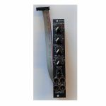
People also bought...
Doepfer A-101-8v Photo Phasing 8-Stage Phase Shifter Vintage Edition Module (black) (phase shifter/effect synth module)
Cat: 950741 Rel: 19 Jun 23 • View all Synth modules
8-stage phase shifter module - 4HP.
Notes: Module A-101-8V is a 8-stage phase shifter which uses light-sensitive resistors (LDR) and is a replica of the Compact Phasing A manufactured by the company Schulte in the seventies. The actual phasing circuit is identical to the historic model. Only the illumination control of the LDRs is different: the A-101-8 uses LEDs to illuminate the LDRs, the historic model used incandescent miniature lamps. And the A-101-8 has no built-in LFO but can be controlled by any external control voltage source (e.g. LFO, ADSR, random, Theremin, ribbon controller, sequencer, midi). The phasing offset (i.e. the base value for the phase shifting) and the modulation depth of the external control signal can be adjusted separately. The Compact Phasing A had no offset control but only a depth control for the built-in LFO. Feedback and mixing ratio of the output signal are set by two controls. The audio input is equipped with an attenuator. The module has two audio outputs available (same as the historic model) and a visual display of the phase shifting.
The module has these controls and in/outputs available:
Control Man. : manual control of the phase shift offset (base value)
Control CV: attenuator for the signal applied to the CV socket
Control Feedb.: Feedback or Resonance (similar function as filter resonance/feedback/emphasis)
Control Mix: sets the mixing ratio between original and phase shift signal appearing at output 1
fully CCW: only the modified input signal appears at output 1 (see note below *)
center: a mixture between the modified input signal and the phase shift signal appears at output 1, that's the standard position for the classical phasing effect
fully CW: the pure phase shifted signal appears at output 1 (e.g. for vibrato effects)
Control Input Level: attenuator for signal applied to the In socket
Socket In: audio input
Socket CV: control voltage input
Socket Out 1: audio output 1 (mix signal)
Socket Out 2: audio output 2 (modified input signal)
LED: visual control of the phase shift
The module has some peculiarities (same as the historic model):
The input signal is processed at first by a pre-stage which outputs a "modified" input signal (*). This signal is not processed by the phase shift stages but is affected by the feedback setting. Only when feedback is set to zero this signal is identical to the input signal. Otherwise it contains feedback components.
This signal is output on socket Out 2.
When both output sockets Out 1 and Out 2 are used as stereo channels one obtains a spatial stereo sound effect.
The same signals is also used for the CCW position of the mix control. With mix control fully CCW the unmodified signal appears only if the feedback control is set to zero. Otherwise it contains feedback components.
The historic model had two audio inputs: one 5-pin DIN socket and a 1/4" jack socket. The DIN socket was intended for high-level line signals. When the 1/4" jack socket was used the amplification of the pre-stage increased by about 100. The 1/4" jack socket was intended for low level signals (e.g. electric guitars or microphones). For this feature the A-101-8 has an internal jumper that can be used to increase the amplification. As long as the module is used within the A-100 system usually the lower amplification is used to avoid distortion.
The 8 photo resistors and LEDs are assembled within an small lightproof box. In addition the pc boards are made of lightproof black material to avoid interfering light from other modules or the bus board.
Power consumption: 30mA at +12 V and 30mA at -12 V
Depth: 45mm
HP : 4
… Read moreThe module has these controls and in/outputs available:
Control Man. : manual control of the phase shift offset (base value)
Control CV: attenuator for the signal applied to the CV socket
Control Feedb.: Feedback or Resonance (similar function as filter resonance/feedback/emphasis)
Control Mix: sets the mixing ratio between original and phase shift signal appearing at output 1
fully CCW: only the modified input signal appears at output 1 (see note below *)
center: a mixture between the modified input signal and the phase shift signal appears at output 1, that's the standard position for the classical phasing effect
fully CW: the pure phase shifted signal appears at output 1 (e.g. for vibrato effects)
Control Input Level: attenuator for signal applied to the In socket
Socket In: audio input
Socket CV: control voltage input
Socket Out 1: audio output 1 (mix signal)
Socket Out 2: audio output 2 (modified input signal)
LED: visual control of the phase shift
The module has some peculiarities (same as the historic model):
The input signal is processed at first by a pre-stage which outputs a "modified" input signal (*). This signal is not processed by the phase shift stages but is affected by the feedback setting. Only when feedback is set to zero this signal is identical to the input signal. Otherwise it contains feedback components.
This signal is output on socket Out 2.
When both output sockets Out 1 and Out 2 are used as stereo channels one obtains a spatial stereo sound effect.
The same signals is also used for the CCW position of the mix control. With mix control fully CCW the unmodified signal appears only if the feedback control is set to zero. Otherwise it contains feedback components.
The historic model had two audio inputs: one 5-pin DIN socket and a 1/4" jack socket. The DIN socket was intended for high-level line signals. When the 1/4" jack socket was used the amplification of the pre-stage increased by about 100. The 1/4" jack socket was intended for low level signals (e.g. electric guitars or microphones). For this feature the A-101-8 has an internal jumper that can be used to increase the amplification. As long as the module is used within the A-100 system usually the lower amplification is used to avoid distortion.
The 8 photo resistors and LEDs are assembled within an small lightproof box. In addition the pc boards are made of lightproof black material to avoid interfering light from other modules or the bus board.
Power consumption: 30mA at +12 V and 30mA at -12 V
Depth: 45mm
HP : 4
out of stock $143.08
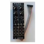
People also bought...
Doepfer A-147-4v Dual VCLFO Dual Voltage Controlled Low Frequency Oscillator Vintage Edition Module (black) (dual/stereo/LFO synth module)
Cat: 950730 Rel: 19 Jun 23 • View all Synth modules
Dual voltage controlled LFO (Low Frequency Oscillator) module - 8HP.
Notes: Module A-147-4V is a dual voltage controlled LFO (Low Frequency Oscillator). Each LFO has the five waveforms triangle, sine, rising and falling sawtooth, as well as rectangle available. The rectangle output features manually adjustable pulsewidth and pulsewidth modulation by means of an external control voltage. The core waveform is triangle. The other waveforms are derived from triangle by means of waveform converters. The frequency of each LFO can be adjusted manually and modulated by means of an external control voltage with associated attenuator and polarity switch. By means of a jumper the basic frequency range of each LFO can selected: about 0.02 Hz (~ 50 seconds) ... 2.5kHz or about 0.0017 Hz(~ 600 seconds) ... 220Hz. That way each LFO can be used also as a VCO with a max. frequency of about 2.5kHz. Each LFO features a reset input which can be used to reset the triangle signal.
The module has these controls and in/outputs available:
Control F : manual control of the frequency, for each LFO the frequency range can be selected by means of a jumper from two values (see technical notes)
frequency coverage of control F in the high frequency range: about 0.075 Hz (~ 13 seconds) ... 1,4kHz
frequency coverage of control F in the low frequency range: about 0.007 Hz (~ 140 seconds) ... 125Hz
Control CV: attenuator for the signal applied to the CV socket, by means of a jumper a small positive voltage can be applied to the switching contact of the /CV/ socket, as long as no patch cable is connected to /CV/ socket the CV control then works as fine control for the frequency
Switch CV Pol.: polarity switch for the signal applied to the socket /CV/
Control PW/PM: combined control for manual and CV control of the rectangle pulsewidth:
when no patch cable is connected to socket /P/ the control is used to adjust the pulsewidth (PW) manually
when a patch cable is connected to socket /P/ the control works as attenuator for the external CV signal with a basic pulsewidth of 50:50.
Socket /CV/: frequency control voltage input, in the factory the module is adjusted so that the sensitivity of this input is exactly 1V/octave when the CV control is fully CW.
Socket /R/: reset input, according to the associated jumper the reset input is edge triggered or level controlled (see technical notes for details)
Socket /P/: pulsewidth control voltage input
Sockets with waveform symbol: output of the waveform in question (triangle, sine, rising and falling sawtooth, rectangle)
The output voltage ranges are about -5V ... +5V (10Vpp), except the rectangle output
For the rectangle output one can choose by means of a jumper if the range is about -5V ... +5V or 0...+10V.
LED: visual control of the LFO (triangle)
The inputs of the module are labelled with white characters on black background (in the text included into two slashes). The outputs are labelled with black characters.
Technical notes and special features:
The basic frequency range of each LFO can be selected by means of a jumper. The settings correspond to two different capacitor values for the VCO circuit. The relation between the two ranges is about 1:11. When the upper range is selected frequencies from about 0.02 Hz up to 2.5kHz can be generated. For the lower range the values are about 0.0017 Hz ... 220Hz. To obtain these full frequency ranges external control voltages are required. With the frequency control F only the frequencies mentioned above are possible.
Apart from that the range for the manual control F can be reduced to obtain a finer resolution. For this a jumper has to be removed. The range of control F is then reduced to about 1:4.5 only.
In the factory the starting voltage of the triangle output after a reset is adjusted to 0V, i.e. the triangle starts from 0V with the rising slope after a reset. By means of a trimming potentiometer the starting voltage can be adjusted to another value (e.g. to -5V).
Another jumper is used to set the reset behaviour to edge triggered or level controlled. When set to edge triggered the rising edge of reset signal is used for the reset (independent of the duration of the "high" state of the reset signal). When set to level controlled the triangle output remains at the starting voltage as long as the reset signal is "high". Only when the reset signal turns "low" the triangle starts.
Power consumption: 80mA at +12 V and 70mA at -12 V
Depth: 45mm
HP : 8
… Read moreThe module has these controls and in/outputs available:
Control F : manual control of the frequency, for each LFO the frequency range can be selected by means of a jumper from two values (see technical notes)
frequency coverage of control F in the high frequency range: about 0.075 Hz (~ 13 seconds) ... 1,4kHz
frequency coverage of control F in the low frequency range: about 0.007 Hz (~ 140 seconds) ... 125Hz
Control CV: attenuator for the signal applied to the CV socket, by means of a jumper a small positive voltage can be applied to the switching contact of the /CV/ socket, as long as no patch cable is connected to /CV/ socket the CV control then works as fine control for the frequency
Switch CV Pol.: polarity switch for the signal applied to the socket /CV/
Control PW/PM: combined control for manual and CV control of the rectangle pulsewidth:
when no patch cable is connected to socket /P/ the control is used to adjust the pulsewidth (PW) manually
when a patch cable is connected to socket /P/ the control works as attenuator for the external CV signal with a basic pulsewidth of 50:50.
Socket /CV/: frequency control voltage input, in the factory the module is adjusted so that the sensitivity of this input is exactly 1V/octave when the CV control is fully CW.
Socket /R/: reset input, according to the associated jumper the reset input is edge triggered or level controlled (see technical notes for details)
Socket /P/: pulsewidth control voltage input
Sockets with waveform symbol: output of the waveform in question (triangle, sine, rising and falling sawtooth, rectangle)
The output voltage ranges are about -5V ... +5V (10Vpp), except the rectangle output
For the rectangle output one can choose by means of a jumper if the range is about -5V ... +5V or 0...+10V.
LED: visual control of the LFO (triangle)
The inputs of the module are labelled with white characters on black background (in the text included into two slashes). The outputs are labelled with black characters.
Technical notes and special features:
The basic frequency range of each LFO can be selected by means of a jumper. The settings correspond to two different capacitor values for the VCO circuit. The relation between the two ranges is about 1:11. When the upper range is selected frequencies from about 0.02 Hz up to 2.5kHz can be generated. For the lower range the values are about 0.0017 Hz ... 220Hz. To obtain these full frequency ranges external control voltages are required. With the frequency control F only the frequencies mentioned above are possible.
Apart from that the range for the manual control F can be reduced to obtain a finer resolution. For this a jumper has to be removed. The range of control F is then reduced to about 1:4.5 only.
In the factory the starting voltage of the triangle output after a reset is adjusted to 0V, i.e. the triangle starts from 0V with the rising slope after a reset. By means of a trimming potentiometer the starting voltage can be adjusted to another value (e.g. to -5V).
Another jumper is used to set the reset behaviour to edge triggered or level controlled. When set to edge triggered the rising edge of reset signal is used for the reset (independent of the duration of the "high" state of the reset signal). When set to level controlled the triangle output remains at the starting voltage as long as the reset signal is "high". Only when the reset signal turns "low" the triangle starts.
Power consumption: 80mA at +12 V and 70mA at -12 V
Depth: 45mm
HP : 8
1 in stock $170.05
Click for better price!
or call +44 20 7424 1960
quote 950730
quote 950730
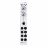
People also bought...
Doepfer A-171-4 Quad Voltage Controlled Slew Limiter Module (quad/slew limiter synth module)
Cat: 945417 Rel: 13 Jun 23 • View all Synth modules
A quad voltage controlled slew limiter (polyphonic portamento) module in 4HP.
Notes: Module A-171-4 is a fourfold voltage controlled slew limiter. It's intended purpose is polyphonic portamento but can be used also for other applications where several slew limiters are required.
The common slew time can be adjusted manually and in addition controlled by an external control voltage. The module uses light-sensitive resistors (LDR). Therefore the slew times are not exactly the same for all units due to the tolerances of the LDRs and the LEDs, which are used to illuminate the LDRs. Inputs and outputs of the slew limiters are buffered to avoid voltage drops. This is especially important for polyphonic portamento applications. Each output can drive several VCOs without the need of external buffers. In addition the slew limiter inputs and outputs are available at internal pin headers for internal pre-wiring of polyphonic patches. As the switching contacts of the sockets are used for the internal pre-patching the internal patch can be overridden by using the sockets at the front panel.
The module has these controls and in/outputs available:
Control Man. : manual control of the slew limiter value (base value)
Control CV: attenuator for the signal applied to the CV socket
Socket CV: control voltage input
Sockets In 1...4: slew limiter inputs
Sockets Out 1...4: slew limiter outputs
LED: visual control of the slew limiter value (dark = long time, bright = short time)
Technical notes:
Each light-sensitive resistor (LDR) forms together with an associated capacitor a simple standard RC network (Resistor/Capacitor network). Input and output of each network are buffered.
The slew time range is about 5 ms ... 10 s (1:2000). Due to the tolerances of the LDRs and the LEDs the slew times vary a bit for each unit. By changing the capacitor values this range can be altered: by lowering the capacitor values the slew limiters can be used as 6dB low pass filters. Increasing the capacitor values result in longer slew times
The 4 photo resistors and LEDs are assembled within an small lighproof box. In addition the pc boards are made of lighproof black material to avoid interfering light from other modules or the bus board.
On the module pc boards two pin headers with 4 pins each are available. These are planned for the internal pre-patching of polyphonic modules:
In 1...4: The pins of this pin header are connected to the switching contacts of the sockets In 1...4. Hereby an internal four-wire connection to the CV outputs of the polyphonic midi-CV-interface A-190-5 can be made. As long as the sockets In 1...4 are not used the internal connection to the A-190-5 is established.
Out 1...4: The pins of this pin header are connected to the outputs Out 1...4. Hereby an internal four-wire connection to the CV inputs of the polyphonic VCO A-111-4 can be realized. If more than one VCO has to be controlled by one output we offer so-called micro multiples.
Dimensions
4 HP
45 mm deep
Current Draw
40 mA +12V
40 mA -12V
… Read moreThe common slew time can be adjusted manually and in addition controlled by an external control voltage. The module uses light-sensitive resistors (LDR). Therefore the slew times are not exactly the same for all units due to the tolerances of the LDRs and the LEDs, which are used to illuminate the LDRs. Inputs and outputs of the slew limiters are buffered to avoid voltage drops. This is especially important for polyphonic portamento applications. Each output can drive several VCOs without the need of external buffers. In addition the slew limiter inputs and outputs are available at internal pin headers for internal pre-wiring of polyphonic patches. As the switching contacts of the sockets are used for the internal pre-patching the internal patch can be overridden by using the sockets at the front panel.
The module has these controls and in/outputs available:
Control Man. : manual control of the slew limiter value (base value)
Control CV: attenuator for the signal applied to the CV socket
Socket CV: control voltage input
Sockets In 1...4: slew limiter inputs
Sockets Out 1...4: slew limiter outputs
LED: visual control of the slew limiter value (dark = long time, bright = short time)
Technical notes:
Each light-sensitive resistor (LDR) forms together with an associated capacitor a simple standard RC network (Resistor/Capacitor network). Input and output of each network are buffered.
The slew time range is about 5 ms ... 10 s (1:2000). Due to the tolerances of the LDRs and the LEDs the slew times vary a bit for each unit. By changing the capacitor values this range can be altered: by lowering the capacitor values the slew limiters can be used as 6dB low pass filters. Increasing the capacitor values result in longer slew times
The 4 photo resistors and LEDs are assembled within an small lighproof box. In addition the pc boards are made of lighproof black material to avoid interfering light from other modules or the bus board.
On the module pc boards two pin headers with 4 pins each are available. These are planned for the internal pre-patching of polyphonic modules:
In 1...4: The pins of this pin header are connected to the switching contacts of the sockets In 1...4. Hereby an internal four-wire connection to the CV outputs of the polyphonic midi-CV-interface A-190-5 can be made. As long as the sockets In 1...4 are not used the internal connection to the A-190-5 is established.
Out 1...4: The pins of this pin header are connected to the outputs Out 1...4. Hereby an internal four-wire connection to the CV inputs of the polyphonic VCO A-111-4 can be realized. If more than one VCO has to be controlled by one output we offer so-called micro multiples.
Dimensions
4 HP
45 mm deep
Current Draw
40 mA +12V
40 mA -12V
out of stock $111.97
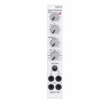
People also bought...
Doepfer A-101-8 Photo Phasing 8-Stage Phase Shifter Module (silver) (phase shifter/effect synth module)
Cat: 945411 Rel: 13 Jun 23 • View all Synth modules
An eight stage phase shifter module in 4HP.
Notes: Module A-101-8 is a 8-stage phase shifter which uses light-sensitive resistors (LDR) and is a replica of the Compact Phasing A manufactured by the company Schulte in the seventies. The actual phasing circuit is identical to the historic model. Only the illumination control of the LDRs is different: the A-101-8 uses LEDs to illuminate the LDRs, the historic model used incandescent miniature lamps. And the A-101-8 has no built-in LFO but can be controlled by any external control voltage source (e.g. LFO, ADSR, random, Theremin, ribbon controller, sequencer, midi). The phasing offset (i.e. the base value for the phase shifting) and the modulation depth of the external control signal can be adjusted separately. The Compact Phasing A had no offset control but only a depth control for the built-in LFO. Feedback and mixing ratio of the output signal are set by two controls. The audio input is equipped with an attenuator. The module has two audio outputs available (same as the historic model) and a visual display of the phase shifting.
The module has these controls and in/outputs available:
Control Man. : manual control of the phase shift offset (base value)
Control CV: attenuator for the signal applied to the CV socket
Control Feedb.: Feedback or Resonance (similar function as filter resonance/feedback/emphasis)
Control Mix: sets the mixing ratio between original and phase shift signal appearing at output 1
fully CCW: only the modified input signal appears at output 1 (see note below *)
center: a mixture between the modified input signal and the phase shift signal appears at output 1, that's the standard position for the classical phasing effect
fully CW: the pure phase shifted signal appears at output 1 (e.g. for vibrato effects)
Control Input Level: attenuator for signal applied to the In socket
Socket In: audio input
Socket CV: control voltage input
Socket Out 1: audio output 1 (mix signal)
Socket Out 2: audio output 2 (modified input signal)
LED: visual control of the phase shift
The module has some peculiarities (same as the historic model):
The input signal is processed at first by a pre-stage which outputs a "modified" input signal (*). This signal is not processed by the phase shift stages but is affected by the feedback setting. Only when feedback is set to zero this signal is identical to the input signal. Otherwise it contains feedback components.
This signal is output on socket Out 2.
When both output sockets Out 1 and Out 2 are used as stereo channels one obtains a spatial stereo sound effect.
The same signals is also used for the CCW position of the mix control. With mix control fully CCW the unmodified signal appears only if the feedback control is set to zero. Otherwise it contains feedback components.
The historic model had two audio inputs: one 5-pin DIN socket and a 1/4" jack socket. The DIN socket was intended for high-level line signals. When the 1/4" jack socket was used the amplification of the pre-stage increased by about 100. The 1/4" jack socket was intended for low level signals (e.g. electric guitars or microphones). For this feature the A-101-8 has an internal jumper that can be used to increase the amplification. As long as the module is used within the A-100 system usually the lower amplification is used to avoid distortion.
The 8 photo resistors and LEDs are assembled within an small lighproof box. In addition the pc boards are made of lighproof black material to avoid interfering light from other modules or the bus board.
Dimensions
4 HP
45 mm deep
Current Draw
30 mA +12V
30 mA -12V
… Read moreThe module has these controls and in/outputs available:
Control Man. : manual control of the phase shift offset (base value)
Control CV: attenuator for the signal applied to the CV socket
Control Feedb.: Feedback or Resonance (similar function as filter resonance/feedback/emphasis)
Control Mix: sets the mixing ratio between original and phase shift signal appearing at output 1
fully CCW: only the modified input signal appears at output 1 (see note below *)
center: a mixture between the modified input signal and the phase shift signal appears at output 1, that's the standard position for the classical phasing effect
fully CW: the pure phase shifted signal appears at output 1 (e.g. for vibrato effects)
Control Input Level: attenuator for signal applied to the In socket
Socket In: audio input
Socket CV: control voltage input
Socket Out 1: audio output 1 (mix signal)
Socket Out 2: audio output 2 (modified input signal)
LED: visual control of the phase shift
The module has some peculiarities (same as the historic model):
The input signal is processed at first by a pre-stage which outputs a "modified" input signal (*). This signal is not processed by the phase shift stages but is affected by the feedback setting. Only when feedback is set to zero this signal is identical to the input signal. Otherwise it contains feedback components.
This signal is output on socket Out 2.
When both output sockets Out 1 and Out 2 are used as stereo channels one obtains a spatial stereo sound effect.
The same signals is also used for the CCW position of the mix control. With mix control fully CCW the unmodified signal appears only if the feedback control is set to zero. Otherwise it contains feedback components.
The historic model had two audio inputs: one 5-pin DIN socket and a 1/4" jack socket. The DIN socket was intended for high-level line signals. When the 1/4" jack socket was used the amplification of the pre-stage increased by about 100. The 1/4" jack socket was intended for low level signals (e.g. electric guitars or microphones). For this feature the A-101-8 has an internal jumper that can be used to increase the amplification. As long as the module is used within the A-100 system usually the lower amplification is used to avoid distortion.
The 8 photo resistors and LEDs are assembled within an small lighproof box. In addition the pc boards are made of lighproof black material to avoid interfering light from other modules or the bus board.
Dimensions
4 HP
45 mm deep
Current Draw
30 mA +12V
30 mA -12V
8 in stock $123.14
Click for better price!
or call +44 20 7424 1960
quote 945411
quote 945411
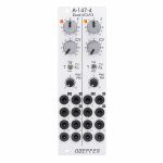
People also bought...
Doepfer A-147-4 Dual VCLFO Dual Voltage Controlled Low Frequency Oscillator Module (silver) (dual/stereo/LFO synth module)
Cat: 945415 Rel: 13 Jun 23 • View all Synth modules
A dual voltage controlled LFO (Low Frequency Oscillator) module in 8HP.
Notes: Module A-147-4 is a dual voltage controlled LFO (Low Frequency Oscillator). Each LFO has the five waveforms triangle, sine, rising and falling sawtooth, as well as rectangle available. The rectangle output features manually adjustable pulsewidth and pulsewidth modulation by means of an external control voltage. The core waveform is triangle. The other waveforms are derived from triangle by means of waveform converters. The frequency of each LFO can be adjusted manually and modulated by means of an external control voltage with associated attenuator and polarity switch. By means of a jumper the basic frequency range of each LFO can selected: about 0.02 Hz (~ 50 seconds) ... 2.5kHz or about 0.0017 Hz(~ 600 seconds) ... 220Hz. That way each LFO can be used also as a VCO with a max. frequency of about 2.5kHz. Each LFO features a reset input which can be used to reset the triangle signal.
The module has these controls and in/outputs available:
Control F : manual control of the frequency, for each LFO the frequency range can be selected by means of a jumper from two values (see technical notes)
frequency coverage of control F in the high frequency range: about 0.075 Hz (~ 13 seconds) ... 1,4kHz
frequency coverage of control F in the low frequency range: about 0.007 Hz (~ 140 seconds) ... 125Hz
Control CV: attenuator for the signal applied to the CV socket, by means of a jumper a small positive voltage can be applied to the switching contact of the /CV/ socket, as long as no patch cable is connected to /CV/ socket the CV control then works as fine control for the frequency
Switch CV Pol.: polarity switch for the signal applied to the socket /CV/
Control PW/PM: combined control for manual and CV control of the rectangle pulsewidth:
when no patch cable is connected to socket /P/ the control is used to adjust the pulsewidth (PW) manually
when a patch cable is connected to socket /P/ the control works as attenuator for the external CV signal with a basic pulsewidth of 50:50.
Socket /CV/: frequency control voltage input, in the factory the module is adjusted so that the sensitivity of this input is exactly 1V/octave when the CV control is fully CW.
Socket /R/: reset input, according to the associated jumper the reset input is edge triggered or level controlled (see technical notes for details)
Socket /P/: pulsewidth control voltage input
Sockets with waveform symbol: output of the waveform in question (triangle, sine, rising and falling sawtooth, rectangle)
The output voltage ranges are about -5V ... +5V (10Vpp), except the rectangle output
For the rectangle output one can choose by means of a jumper if the range is about -5V ... +5V or 0...+10V.
LED: visual control of the LFO (triangle)
The inputs of the module are labelled with white characters on black background (in the text included into two slashes). The outputs are labelled with black characters.
Technical notes and special features:
The basic frequency range of each LFO can be selected by means of a jumper. The settings correspond to two different capacitor values for the VCO circuit. The relation between the two ranges is about 1:11. When the upper range is selected frequencies from about 0.02 Hz up to 2.5kHz can be generated. For the lower range the values are about 0.0017 Hz ... 220Hz. To obtain these full frequency ranges external control voltages are required. With the frequency control F only the frequencies mentioned above are possible.
Apart from that the range for the manual control F can be reduced to obtain a finer resolutuion. For this a jumper has to be removed. The range of control F is then reduced to about 1:4.5 only.
In the factory the starting voltage of the triangle output after a reset is adjusted to 0V, i.e. the triangle starts from 0V with the rising slope after a reset. By means of a trimming potentiometer the starting voltage can be adjusted to another value (e.g. to -5V).
Another jumper is used to set the reset behaviour to edge triggered or level controlled. When set to edge triggered the rising edge of reset signal is used for the reset (independent of the duration of the "high" state of the reset signal). When set to level controlled the triangle output remains at the starting voltage as long as the reset signal is "high". Only when the reset signal turns "low" the triangle starts.
Dimensions
8 HP
45 mm deep
Current Draw
80 mA +12V
70 mA -12V
… Read moreThe module has these controls and in/outputs available:
Control F : manual control of the frequency, for each LFO the frequency range can be selected by means of a jumper from two values (see technical notes)
frequency coverage of control F in the high frequency range: about 0.075 Hz (~ 13 seconds) ... 1,4kHz
frequency coverage of control F in the low frequency range: about 0.007 Hz (~ 140 seconds) ... 125Hz
Control CV: attenuator for the signal applied to the CV socket, by means of a jumper a small positive voltage can be applied to the switching contact of the /CV/ socket, as long as no patch cable is connected to /CV/ socket the CV control then works as fine control for the frequency
Switch CV Pol.: polarity switch for the signal applied to the socket /CV/
Control PW/PM: combined control for manual and CV control of the rectangle pulsewidth:
when no patch cable is connected to socket /P/ the control is used to adjust the pulsewidth (PW) manually
when a patch cable is connected to socket /P/ the control works as attenuator for the external CV signal with a basic pulsewidth of 50:50.
Socket /CV/: frequency control voltage input, in the factory the module is adjusted so that the sensitivity of this input is exactly 1V/octave when the CV control is fully CW.
Socket /R/: reset input, according to the associated jumper the reset input is edge triggered or level controlled (see technical notes for details)
Socket /P/: pulsewidth control voltage input
Sockets with waveform symbol: output of the waveform in question (triangle, sine, rising and falling sawtooth, rectangle)
The output voltage ranges are about -5V ... +5V (10Vpp), except the rectangle output
For the rectangle output one can choose by means of a jumper if the range is about -5V ... +5V or 0...+10V.
LED: visual control of the LFO (triangle)
The inputs of the module are labelled with white characters on black background (in the text included into two slashes). The outputs are labelled with black characters.
Technical notes and special features:
The basic frequency range of each LFO can be selected by means of a jumper. The settings correspond to two different capacitor values for the VCO circuit. The relation between the two ranges is about 1:11. When the upper range is selected frequencies from about 0.02 Hz up to 2.5kHz can be generated. For the lower range the values are about 0.0017 Hz ... 220Hz. To obtain these full frequency ranges external control voltages are required. With the frequency control F only the frequencies mentioned above are possible.
Apart from that the range for the manual control F can be reduced to obtain a finer resolutuion. For this a jumper has to be removed. The range of control F is then reduced to about 1:4.5 only.
In the factory the starting voltage of the triangle output after a reset is adjusted to 0V, i.e. the triangle starts from 0V with the rising slope after a reset. By means of a trimming potentiometer the starting voltage can be adjusted to another value (e.g. to -5V).
Another jumper is used to set the reset behaviour to edge triggered or level controlled. When set to edge triggered the rising edge of reset signal is used for the reset (independent of the duration of the "high" state of the reset signal). When set to level controlled the triangle output remains at the starting voltage as long as the reset signal is "high". Only when the reset signal turns "low" the triangle starts.
Dimensions
8 HP
45 mm deep
Current Draw
80 mA +12V
70 mA -12V
1 in stock $156.77
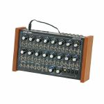
People also bought...
Doepfer Dark Time MIDI/USB Analogue Sequencer (white & blue LED version, supplied with 2 pin Euro plug) (B-STOCK) (MIDI/USB sequencer)
Cat: 926156 Rel: 01 Jan 90 • View all Sequencers
B-STOCK: Original box damaged, product is in different packagaing but is in perfect working order
Notes: ***B-STOCK: Original box damaged, product is in different packagaing but is in perfect working order***
Iconic analogue step sequencer from modular innovators Doepfer. Compatible with all MIDI or CV/gate synths, allowing a huge range of programming and sequencing options, plus real-time tweaking. A firm Juno favourite.
Supplier's notes:
Dark Time is an 2x8 step analogue sequencer with CV/Gate, USB and MIDI interface. It is intended as an add-on for the Dark Energy but may be used in combination with other MIDI, USB or CV/Gate equipment too.
… Read moreIconic analogue step sequencer from modular innovators Doepfer. Compatible with all MIDI or CV/gate synths, allowing a huge range of programming and sequencing options, plus real-time tweaking. A firm Juno favourite.
Supplier's notes:
Dark Time is an 2x8 step analogue sequencer with CV/Gate, USB and MIDI interface. It is intended as an add-on for the Dark Energy but may be used in combination with other MIDI, USB or CV/Gate equipment too.
out of stock $440.89
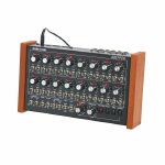
People also bought...
Doepfer Dark Time MIDI/USB Analogue Sequencer (red LED version, supplied with 2 pin Euro plug) (B-STOCK) (MIDI/USB sequencer)
Cat: 926166 Rel: 01 Jan 90 • View all Sequencers
B-STOCK: Original box damaged, product is in different packagaing but in perfect working order
Notes: ***B-STOCK: Original box damaged, product is in different packagaing but in perfect working order***
Dark Time is an 2x8 step analogue sequencer with CV/Gate, USB and MIDI interface. It is intended as an add-on for the Dark Energy but may be used in combination with other MIDI, USB or CV/Gate equipment too.
… Read moreDark Time is an 2x8 step analogue sequencer with CV/Gate, USB and MIDI interface. It is intended as an add-on for the Dark Energy but may be used in combination with other MIDI, USB or CV/Gate equipment too.
out of stock $365.41
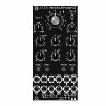
People also bought...
Doepfer A-121sV Stereo Multimode Filter Vintage Edition Module (black) (B-STOCK) (dual/stereo/filter synth module)
Cat: 924238 Rel: 01 Jan 90 • View all Synth modules
B-STOCK: Box opened, but product is in excellent condition and in perfect working order
Notes: ***B-STOCK: Box opened, but product is in excellent condition and in perfect working order***
Module A-121s is a dual multimode filter which can be used for stereo applications as well as for parallel or serial organized dual mono filters. The core is a 12dB multimode filter identical to the modules A-121-2 and A-121-3. The selection of the filter type is continuously from lowpass via notch and highpass to bandpass. We attached great importance to the usability of the manual controls and CV inputs for both stereo and dual mono applications. For the filter parameters frequency (F), resonance (Q) and type (T) common controls and CV inputs as well as single controls and CV inputs are available. For the filter frequency in addition a manual control and CV input for the filter spread (frequency difference or delta F) is available.
Controls:
F: master frequency control for both filters (large knob)
Type 1 / Type 2: filter type panning/morphing L-N-H-B
Link to 1: Toggle switch so that Type 1 also controls type of filter 2 (i.e. simultaneous filter type control for both filters)
SFM1 / SFM2: Single Frequency Modulation controls (polarizers), connected to the corresponding sockets SFM1/SFM2 (socket SFM1 is normalled to a fixed positive voltage, SFM2 is normalled to SFM1, that way the controls SFM1/SFM2 work as frequency controls for each filter provided that no modulation signals are patched to the SFM1/SFM2 sockets)
CFM: common frequency control, controls two VC-polarizers which process the signals connected to the two sockets CFM1/CFM2, CFM2 is normalled to CFM1, that way also the same modulation signal (e.g. an envelope generator) can be used for both filters and the level controlled simultaneously by the CFM control
Delta F: controls the difference between the frequencies of the two filters manually (frequency "spread"), at centre position the frequencies are the same
Delta FM: controls the level of the Delta FM signal (socket), which allows to control the spread between the frequencies also by an external control voltage (e.g. by an LFO or ADSR)
Q: controls the resonance of both filters simultaneously
Level 1 / Level 2: attenuators for the two audio inputs
QM/TM1, QM/TM2: attenuators for the modulation inputs QM/TM1 and QM/TM2
Sockets:
In1 / In2: audio inputs (In2 is normalled to In1)
Out1 / Out2: audio outputs
F: common frequency control input for both filters (~ 1V/oct)
Delta FM: Control voltage for frequency spread, processed by the polarizer Delta FM
SFM1 / SFM2: single frequency modulation inputs, processed by the polarizers SFM1 and SFM2, SFM1 is normalled to a fixed positive voltage, SFM2 is normalled to SFM1#
CFM1 / CFM2: common frequency modulation inputs, processed by the two voltage controlled polarizers controlled by CFM knob, CFM2 is normalled to CFM1
QM/TM1, QM/TM2: the addressing of these sockets/attenuators is defined by internal jumpers. QM means Q modulation (i.e. resonance modulation), TM means filter type modulation (QM1 = resonance modulation filter 1, QM2 = resonance modulation filter 2, TM1 = filter type modulation filter 1, TM2 = filter type modulation filter 2), socket QM/TM1 is normalled to a fixed positive voltage, QM/TM2 is normalled to QM/TM1
A 45 degrees triangle next to a socket means that the switching contact of the socket is normalled to a fixed positive voltage (SFM1, QM/TM1).
A vertical triangle indicates the normalling of two sockets (In1>In2, SFM1>SFM2, CFM1>CFM2, QM/TM1>QM/TM2).
If the filters do not behave as expected please pay attention to these peculiarities:
For the controls SFM1, SFM2, CFM, Delta F and Delta FM the centre position is the neutral position as these are polarizers. If the filter behaves unexpected these controls should be set to centre positions for the time being.
For the controls F, Q, Level 1, Level 2, QM/TM1 und QM/TM2 the fully CCW position is the neutral position as these are standard attenuators. If the filter behaves unexpected at least the controls QM/TM1 and QM/TM2 should be set to fully CCW. Via the normalling of the sockets QM/TM1 and QM/TM2 and the associated controls the filter parameters adjusted by the major controls (e.g. Type 1, Type 2 or Q) may be overwritten.
By means of small circles at the bottom right side of the front panel the user can mark the function of the QM/TM inputs. These assignments are possible:
QM/TM1 controls QM1, QM/TM2 controls QM2, the filter types are not controlled by external CVs
QM/TM1 controls TM1, QM/TM2 controls TM2, the resonances are not controlled by external CVs
QM/TM1 controls QM1 and QM2 simultaneously, QM/TM2 controls TM1 and TM2 simultaneously
… Read moreModule A-121s is a dual multimode filter which can be used for stereo applications as well as for parallel or serial organized dual mono filters. The core is a 12dB multimode filter identical to the modules A-121-2 and A-121-3. The selection of the filter type is continuously from lowpass via notch and highpass to bandpass. We attached great importance to the usability of the manual controls and CV inputs for both stereo and dual mono applications. For the filter parameters frequency (F), resonance (Q) and type (T) common controls and CV inputs as well as single controls and CV inputs are available. For the filter frequency in addition a manual control and CV input for the filter spread (frequency difference or delta F) is available.
Controls:
F: master frequency control for both filters (large knob)
Type 1 / Type 2: filter type panning/morphing L-N-H-B
Link to 1: Toggle switch so that Type 1 also controls type of filter 2 (i.e. simultaneous filter type control for both filters)
SFM1 / SFM2: Single Frequency Modulation controls (polarizers), connected to the corresponding sockets SFM1/SFM2 (socket SFM1 is normalled to a fixed positive voltage, SFM2 is normalled to SFM1, that way the controls SFM1/SFM2 work as frequency controls for each filter provided that no modulation signals are patched to the SFM1/SFM2 sockets)
CFM: common frequency control, controls two VC-polarizers which process the signals connected to the two sockets CFM1/CFM2, CFM2 is normalled to CFM1, that way also the same modulation signal (e.g. an envelope generator) can be used for both filters and the level controlled simultaneously by the CFM control
Delta F: controls the difference between the frequencies of the two filters manually (frequency "spread"), at centre position the frequencies are the same
Delta FM: controls the level of the Delta FM signal (socket), which allows to control the spread between the frequencies also by an external control voltage (e.g. by an LFO or ADSR)
Q: controls the resonance of both filters simultaneously
Level 1 / Level 2: attenuators for the two audio inputs
QM/TM1, QM/TM2: attenuators for the modulation inputs QM/TM1 and QM/TM2
Sockets:
In1 / In2: audio inputs (In2 is normalled to In1)
Out1 / Out2: audio outputs
F: common frequency control input for both filters (~ 1V/oct)
Delta FM: Control voltage for frequency spread, processed by the polarizer Delta FM
SFM1 / SFM2: single frequency modulation inputs, processed by the polarizers SFM1 and SFM2, SFM1 is normalled to a fixed positive voltage, SFM2 is normalled to SFM1#
CFM1 / CFM2: common frequency modulation inputs, processed by the two voltage controlled polarizers controlled by CFM knob, CFM2 is normalled to CFM1
QM/TM1, QM/TM2: the addressing of these sockets/attenuators is defined by internal jumpers. QM means Q modulation (i.e. resonance modulation), TM means filter type modulation (QM1 = resonance modulation filter 1, QM2 = resonance modulation filter 2, TM1 = filter type modulation filter 1, TM2 = filter type modulation filter 2), socket QM/TM1 is normalled to a fixed positive voltage, QM/TM2 is normalled to QM/TM1
A 45 degrees triangle next to a socket means that the switching contact of the socket is normalled to a fixed positive voltage (SFM1, QM/TM1).
A vertical triangle indicates the normalling of two sockets (In1>In2, SFM1>SFM2, CFM1>CFM2, QM/TM1>QM/TM2).
If the filters do not behave as expected please pay attention to these peculiarities:
For the controls SFM1, SFM2, CFM, Delta F and Delta FM the centre position is the neutral position as these are polarizers. If the filter behaves unexpected these controls should be set to centre positions for the time being.
For the controls F, Q, Level 1, Level 2, QM/TM1 und QM/TM2 the fully CCW position is the neutral position as these are standard attenuators. If the filter behaves unexpected at least the controls QM/TM1 and QM/TM2 should be set to fully CCW. Via the normalling of the sockets QM/TM1 and QM/TM2 and the associated controls the filter parameters adjusted by the major controls (e.g. Type 1, Type 2 or Q) may be overwritten.
By means of small circles at the bottom right side of the front panel the user can mark the function of the QM/TM inputs. These assignments are possible:
QM/TM1 controls QM1, QM/TM2 controls QM2, the filter types are not controlled by external CVs
QM/TM1 controls TM1, QM/TM2 controls TM2, the resonances are not controlled by external CVs
QM/TM1 controls QM1 and QM2 simultaneously, QM/TM2 controls TM1 and TM2 simultaneously
1 in stock $217.03

People also bought...
Doepfer A-183-5 Quad Attenuator Slim Line Series Module (silver) (attenuator/quad synth module)
Cat: 880264 Rel: 05 Oct 22 • View all Synth modules
Module A-183-5 is a simple passive quad attenuator.
Notes: Module A-183-5 is a simple passive quad attenuator. Passive means in this context, that each unit is made of two sockets and a 50k linear potentiometer only. There are no active parts like amplifiers or buffers and no power supply is required.
This is how the A-183-5 works: At the output socket appears the attenuated input signal, i.e. zero level at the fully CCW position and max. level and the fully CW position.
Applications:
Adjustable level of CV or audio signals to control other modules that do not have attenuators available.
Dimensions
4 HP
20 mm deep
… Read moreThis is how the A-183-5 works: At the output socket appears the attenuated input signal, i.e. zero level at the fully CCW position and max. level and the fully CW position.
Applications:
Adjustable level of CV or audio signals to control other modules that do not have attenuators available.
Dimensions
4 HP
20 mm deep
out of stock $69.47

People also bought...
Doepfer A-138j Inverting/Interrupting Mixer (Janus Mixer) Slim Line Series Module (silver) (mixer/utility/polarizer/quad synth module)
Cat: 880272 Rel: 05 Oct 22 • View all Synth modules
Module A-138j is a four channel mixer with an additional polarity/mute switch for each input.
Notes: Module A-138j is a four channel mixer with an additional polarity/mute switch for each input. In the upper position of the corresponding switch the inverted signal is used. In the center position the input in question is turned off (mute) and in the lower position the "normal" (i.e. non-inverted) signal is used. The inverting of signals is used especially for control voltage signals (e.g. LFO, ADSR). But even for corellated audio signals this feature is useful. For example for feedback applications or the mixing of original and processed signals (e.g. original and filtered signal to obtain new filter types).
Channel 1 features in addition an Offset function: provided that no plug is inserted into socket Input 1 control Lev.1 generates an adjustable DC voltage (positive or negative depending upon the position of the polarity switch).
On top of that the module is equipped with two types of single outputs and a dual mix output. All inputs and outputs are DC coupled. Consequently the VCAs can be used to mix both audio and control voltages.
Each input is - apart from the polarity/mute switch - equipped with a linear attenuator. The amplification range is 0....1.
The single outputs offer the attenuated and possibly inverted/muted signal of the channel in question. Two version of single outputs are available:
Single Output A: If a plug is inserted into the single output "A" socket the channel in question is removed from the sum signal.
Single Output B: If a plug is inserted into the single output "B" socket the channel in question is not removed from the sum signal. This type of single outputs is available only for the channels 1 and 2.
Based on this flexible structure each channel can be used also individually as attenuator or inverter (i.e. without mixer function).
The output is twice available (two sockets, hard-wired like a multiple).
The distances between the controls and sockets are smaller as for the standard A-100 modules and rubberized small-sized knobs are used. In return the front panel has 6 HP width only. The module is primarily planned for applications where only limited space is available.
Power consumption: 20mA at +12 V and 20mA at -12 V
Depth: 40mm
HP : 6
… Read moreChannel 1 features in addition an Offset function: provided that no plug is inserted into socket Input 1 control Lev.1 generates an adjustable DC voltage (positive or negative depending upon the position of the polarity switch).
On top of that the module is equipped with two types of single outputs and a dual mix output. All inputs and outputs are DC coupled. Consequently the VCAs can be used to mix both audio and control voltages.
Each input is - apart from the polarity/mute switch - equipped with a linear attenuator. The amplification range is 0....1.
The single outputs offer the attenuated and possibly inverted/muted signal of the channel in question. Two version of single outputs are available:
Single Output A: If a plug is inserted into the single output "A" socket the channel in question is removed from the sum signal.
Single Output B: If a plug is inserted into the single output "B" socket the channel in question is not removed from the sum signal. This type of single outputs is available only for the channels 1 and 2.
Based on this flexible structure each channel can be used also individually as attenuator or inverter (i.e. without mixer function).
The output is twice available (two sockets, hard-wired like a multiple).
The distances between the controls and sockets are smaller as for the standard A-100 modules and rubberized small-sized knobs are used. In return the front panel has 6 HP width only. The module is primarily planned for applications where only limited space is available.
Power consumption: 20mA at +12 V and 20mA at -12 V
Depth: 40mm
HP : 6
out of stock $100.58
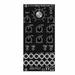
People also bought...
Doepfer A-121sV Stereo Multimode Filter Vintage Edition Module (black) (dual/stereo/filter synth module)
Cat: 880251 Rel: 18 Aug 22 • View all Synth modules
Module A-121s is a dual multimode filter which can be used for stereo applications as well as for parallel or serial organized dual mono filters.
Notes: Module A-121s is a dual multimode filter which can be used for stereo applications as well as for parallel or serial organized dual mono filters. The core is a 12dB multimode filter identical to the modules A-121-2 and A-121-3. The selection of the filter type is continuously from lowpass via notch and highpass to bandpass. We attached great importance to the usability of the manual controls and CV inputs for both stereo and dual mono applications. For the filter parameters frequency (F), resonance (Q) and type (T) common controls and CV inputs as well as single controls and CV inputs are available. For the filter frequency in addition a manual control and CV input for the filter spread (frequency difference or delta F) is available.
Controls:
F: master frequency control for both filters (large knob)
Type 1 / Type 2: filter type panning/morphing L-N-H-B
Link to 1: Toggle switch so that Type 1 also controls type of filter 2 (i.e. simultaneous filter type control for both filters)
SFM1 / SFM2: Single Frequency Modulation controls (polarizers), connected to the corresponding sockets SFM1/SFM2 (socket SFM1 is normalled to a fixed positive voltage, SFM2 is normalled to SFM1, that way the controls SFM1/SFM2 work as frequency controls for each filter provided that no modulation signals are patched to the SFM1/SFM2 sockets)
CFM: common frequency control, controls two VC-polarizers which process the signals connected to the two sockets CFM1/CFM2, CFM2 is normalled to CFM1, that way also the same modulation signal (e.g. an envelope generator) can be used for both filters and the level controlled simultaneously by the CFM control
Delta F: controls the difference between the frequencies of the two filters manually (frequency "spread"), at centre position the frequencies are the same
Delta FM: controls the level of the Delta FM signal (socket), which allows to control the spread between the frequencies also by an external control voltage (e.g. by an LFO or ADSR)
Q: controls the resonance of both filters simultaneously
Level 1 / Level 2: attenuators for the two audio inputs
QM/TM1, QM/TM2: attenuators for the modulation inputs QM/TM1 and QM/TM2
Sockets:
In1 / In2: audio inputs (In2 is normalled to In1)
Out1 / Out2: audio outputs
F: common frequency control input for both filters (~ 1V/oct)
Delta FM: Control voltage for frequency spread, processed by the polarizer Delta FM
SFM1 / SFM2: single frequency modulation inputs, processed by the polarizers SFM1 and SFM2, SFM1 is normalled to a fixed positive voltage, SFM2 is normalled to SFM1#
CFM1 / CFM2: common frequency modulation inputs, processed by the two voltage controlled polarizers controlled by CFM knob, CFM2 is normalled to CFM1
QM/TM1, QM/TM2: the addressing of these sockets/attenuators is defined by internal jumpers. QM means Q modulation (i.e. resonance modulation), TM means filter type modulation (QM1 = resonance modulation filter 1, QM2 = resonance modulation filter 2, TM1 = filter type modulation filter 1, TM2 = filter type modulation filter 2), socket QM/TM1 is normalled to a fixed positive voltage, QM/TM2 is normalled to QM/TM1
A 45 degrees triangle next to a socket means that the switching contact of the socket is normalled to a fixed positive voltage (SFM1, QM/TM1).
A vertical triangle indicates the normalling of two sockets (In1>In2, SFM1>SFM2, CFM1>CFM2, QM/TM1>QM/TM2).
If the filters do not behave as expected please pay attention to these peculiarities:
For the controls SFM1, SFM2, CFM, Delta F and Delta FM the centre position is the neutral position as these are polarizers. If the filter behaves unexpected these controls should be set to centre positions for the time being.
For the controls F, Q, Level 1, Level 2, QM/TM1 und QM/TM2 the fully CCW position is the neutral position as these are standard attenuators. If the filter behaves unexpected at least the controls QM/TM1 and QM/TM2 should be set to fully CCW. Via the normalling of the sockets QM/TM1 and QM/TM2 and the associated controls the filter parameters adjusted by the major controls (e.g. Type 1, Type 2 or Q) may be overwritten.
By means of small circles at the bottom right side of the front panel the user can mark the function of the QM/TM inputs. These assignments are possible:
QM/TM1 controls QM1, QM/TM2 controls QM2, the filter types are not controlled by external CVs
QM/TM1 controls TM1, QM/TM2 controls TM2, the resonances are not controlled by external CVs
QM/TM1 controls QM1 and QM2 simultaneously, QM/TM2 controls TM1 and TM2 simultaneously
… Read moreControls:
F: master frequency control for both filters (large knob)
Type 1 / Type 2: filter type panning/morphing L-N-H-B
Link to 1: Toggle switch so that Type 1 also controls type of filter 2 (i.e. simultaneous filter type control for both filters)
SFM1 / SFM2: Single Frequency Modulation controls (polarizers), connected to the corresponding sockets SFM1/SFM2 (socket SFM1 is normalled to a fixed positive voltage, SFM2 is normalled to SFM1, that way the controls SFM1/SFM2 work as frequency controls for each filter provided that no modulation signals are patched to the SFM1/SFM2 sockets)
CFM: common frequency control, controls two VC-polarizers which process the signals connected to the two sockets CFM1/CFM2, CFM2 is normalled to CFM1, that way also the same modulation signal (e.g. an envelope generator) can be used for both filters and the level controlled simultaneously by the CFM control
Delta F: controls the difference between the frequencies of the two filters manually (frequency "spread"), at centre position the frequencies are the same
Delta FM: controls the level of the Delta FM signal (socket), which allows to control the spread between the frequencies also by an external control voltage (e.g. by an LFO or ADSR)
Q: controls the resonance of both filters simultaneously
Level 1 / Level 2: attenuators for the two audio inputs
QM/TM1, QM/TM2: attenuators for the modulation inputs QM/TM1 and QM/TM2
Sockets:
In1 / In2: audio inputs (In2 is normalled to In1)
Out1 / Out2: audio outputs
F: common frequency control input for both filters (~ 1V/oct)
Delta FM: Control voltage for frequency spread, processed by the polarizer Delta FM
SFM1 / SFM2: single frequency modulation inputs, processed by the polarizers SFM1 and SFM2, SFM1 is normalled to a fixed positive voltage, SFM2 is normalled to SFM1#
CFM1 / CFM2: common frequency modulation inputs, processed by the two voltage controlled polarizers controlled by CFM knob, CFM2 is normalled to CFM1
QM/TM1, QM/TM2: the addressing of these sockets/attenuators is defined by internal jumpers. QM means Q modulation (i.e. resonance modulation), TM means filter type modulation (QM1 = resonance modulation filter 1, QM2 = resonance modulation filter 2, TM1 = filter type modulation filter 1, TM2 = filter type modulation filter 2), socket QM/TM1 is normalled to a fixed positive voltage, QM/TM2 is normalled to QM/TM1
A 45 degrees triangle next to a socket means that the switching contact of the socket is normalled to a fixed positive voltage (SFM1, QM/TM1).
A vertical triangle indicates the normalling of two sockets (In1>In2, SFM1>SFM2, CFM1>CFM2, QM/TM1>QM/TM2).
If the filters do not behave as expected please pay attention to these peculiarities:
For the controls SFM1, SFM2, CFM, Delta F and Delta FM the centre position is the neutral position as these are polarizers. If the filter behaves unexpected these controls should be set to centre positions for the time being.
For the controls F, Q, Level 1, Level 2, QM/TM1 und QM/TM2 the fully CCW position is the neutral position as these are standard attenuators. If the filter behaves unexpected at least the controls QM/TM1 and QM/TM2 should be set to fully CCW. Via the normalling of the sockets QM/TM1 and QM/TM2 and the associated controls the filter parameters adjusted by the major controls (e.g. Type 1, Type 2 or Q) may be overwritten.
By means of small circles at the bottom right side of the front panel the user can mark the function of the QM/TM inputs. These assignments are possible:
QM/TM1 controls QM1, QM/TM2 controls QM2, the filter types are not controlled by external CVs
QM/TM1 controls TM1, QM/TM2 controls TM2, the resonances are not controlled by external CVs
QM/TM1 controls QM1 and QM2 simultaneously, QM/TM2 controls TM1 and TM2 simultaneously
1 in stock $241.59
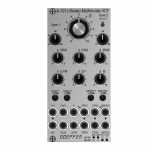
People also bought...
Doepfer A-121s Stereo Multimode Filter Module (silver) (dual/stereo/filter synth module)
Cat: 880248 Rel: 19 Aug 22 • View all Synth modules
Module A-121s is a dual multimode filter which can be used for stereo applications as well as for parallel or serial organized dual mono filters.
Notes: Module A-121s is a dual multimode filter which can be used for stereo applications as well as for parallel or serial organized dual mono filters. The core is a 12dB multimode filter identical to the modules A-121-2 and A-121-3. The selection of the filter type is continuously from lowpass via notch and highpass to bandpass. We attached great importance to the usability of the manual controls and CV inputs for both stereo and dual mono applications. For the filter parameters frequency (F), resonance (Q) and type (T) common controls and CV inputs as well as single controls and CV inputs are available. For the filter frequency in addition a manual control and CV input for the filter spread (frequency difference or delta F) is available.
Controls:
F: master frequency control for both filters (large knob)
Type 1 / Type 2: filter type panning/morphing L-N-H-B
Link to 1: Toggle switch so that Type 1 also controls type of filter 2 (i.e. simultaneous filter type control for both filters)
SFM1 / SFM2: Single Frequency Modulation controls (polarizers), connected to the corresponding sockets SFM1/SFM2 (socket SFM1 is normalled to a fixed positive voltage, SFM2 is normalled to SFM1, that way the controls SFM1/SFM2 work as frequency controls for each filter provided that no modulation signals are patched to the SFM1/SFM2 sockets)
CFM: common frequency control, controls two VC-polarizers which process the signals connected to the two sockets CFM1/CFM2, CFM2 is normalled to CFM1, that way also the same modulation signal (e.g. an envelope generator) can be used for both filters and the level controlled simultaneously by the CFM control
Delta F: controls the difference between the frequencies of the two filters manually (frequency "spread"), at centre position the frequencies are the same
Delta FM: controls the level of the Delta FM signal (socket), which allows to control the spread between the frequencies also by an external control voltage (e.g. by an LFO or ADSR)
Q: controls the resonance of both filters simultaneously
Level 1 / Level 2: attenuators for the two audio inputs
QM/TM1, QM/TM2: attenuators for the modulation inputs QM/TM1 and QM/TM2
Sockets:
In1 / In2: audio inputs (In2 is normalled to In1)
Out1 / Out2: audio outputs
F: common frequency control input for both filters (~ 1V/oct)
Delta FM: Control voltage for frequency spread, processed by the polarizer Delta FM
SFM1 / SFM2: single frequency modulation inputs, processed by the polarizers SFM1 and SFM2, SFM1 is normalled to a fixed positive voltage, SFM2 is normalled to SFM1#
CFM1 / CFM2: common frequency modulation inputs, processed by the two voltage controlled polarizers controlled by CFM knob, CFM2 is normalled to CFM1
QM/TM1, QM/TM2: the addressing of these sockets/attenuators is defined by internal jumpers. QM means Q modulation (i.e. resonance modulation), TM means filter type modulation (QM1 = resonance modulation filter 1, QM2 = resonance modulation filter 2, TM1 = filter type modulation filter 1, TM2 = filter type modulation filter 2), socket QM/TM1 is normalled to a fixed positive voltage, QM/TM2 is normalled to QM/TM1
A 45 degrees triangle next to a socket means that the switching contact of the socket is normalled to a fixed positive voltage (SFM1, QM/TM1).
A vertical triangle indicates the normalling of two sockets (In1>In2, SFM1>SFM2, CFM1>CFM2, QM/TM1>QM/TM2).
If the filters do not behave as expected please pay attention to these peculiarities:
For the controls SFM1, SFM2, CFM, Delta F and Delta FM the centre position is the neutral position as these are polarizers. If the filter behaves unexpected these controls should be set to centre positions for the time being.
For the controls F, Q, Level 1, Level 2, QM/TM1 und QM/TM2 the fully CCW position is the neutral position as these are standard attenuators. If the filter behaves unexpected at least the controls QM/TM1 and QM/TM2 should be set to fully CCW. Via the normalling of the sockets QM/TM1 and QM/TM2 and the associated controls the filter parameters adjusted by the major controls (e.g. Type 1, Type 2 or Q) may be overwritten.
By means of small circles at the bottom right side of the front panel the user can mark the function of the QM/TM inputs. These assignments are possible:
QM/TM1 controls QM1, QM/TM2 controls QM2, the filter types are not controlled by external CVs
QM/TM1 controls TM1, QM/TM2 controls TM2, the resonances are not controlled by external CVs
QM/TM1 controls QM1 and QM2 simultaneously, QM/TM2 controls TM1 and TM2 simultaneously
Depth: 45mm
HP : 12
… Read moreControls:
F: master frequency control for both filters (large knob)
Type 1 / Type 2: filter type panning/morphing L-N-H-B
Link to 1: Toggle switch so that Type 1 also controls type of filter 2 (i.e. simultaneous filter type control for both filters)
SFM1 / SFM2: Single Frequency Modulation controls (polarizers), connected to the corresponding sockets SFM1/SFM2 (socket SFM1 is normalled to a fixed positive voltage, SFM2 is normalled to SFM1, that way the controls SFM1/SFM2 work as frequency controls for each filter provided that no modulation signals are patched to the SFM1/SFM2 sockets)
CFM: common frequency control, controls two VC-polarizers which process the signals connected to the two sockets CFM1/CFM2, CFM2 is normalled to CFM1, that way also the same modulation signal (e.g. an envelope generator) can be used for both filters and the level controlled simultaneously by the CFM control
Delta F: controls the difference between the frequencies of the two filters manually (frequency "spread"), at centre position the frequencies are the same
Delta FM: controls the level of the Delta FM signal (socket), which allows to control the spread between the frequencies also by an external control voltage (e.g. by an LFO or ADSR)
Q: controls the resonance of both filters simultaneously
Level 1 / Level 2: attenuators for the two audio inputs
QM/TM1, QM/TM2: attenuators for the modulation inputs QM/TM1 and QM/TM2
Sockets:
In1 / In2: audio inputs (In2 is normalled to In1)
Out1 / Out2: audio outputs
F: common frequency control input for both filters (~ 1V/oct)
Delta FM: Control voltage for frequency spread, processed by the polarizer Delta FM
SFM1 / SFM2: single frequency modulation inputs, processed by the polarizers SFM1 and SFM2, SFM1 is normalled to a fixed positive voltage, SFM2 is normalled to SFM1#
CFM1 / CFM2: common frequency modulation inputs, processed by the two voltage controlled polarizers controlled by CFM knob, CFM2 is normalled to CFM1
QM/TM1, QM/TM2: the addressing of these sockets/attenuators is defined by internal jumpers. QM means Q modulation (i.e. resonance modulation), TM means filter type modulation (QM1 = resonance modulation filter 1, QM2 = resonance modulation filter 2, TM1 = filter type modulation filter 1, TM2 = filter type modulation filter 2), socket QM/TM1 is normalled to a fixed positive voltage, QM/TM2 is normalled to QM/TM1
A 45 degrees triangle next to a socket means that the switching contact of the socket is normalled to a fixed positive voltage (SFM1, QM/TM1).
A vertical triangle indicates the normalling of two sockets (In1>In2, SFM1>SFM2, CFM1>CFM2, QM/TM1>QM/TM2).
If the filters do not behave as expected please pay attention to these peculiarities:
For the controls SFM1, SFM2, CFM, Delta F and Delta FM the centre position is the neutral position as these are polarizers. If the filter behaves unexpected these controls should be set to centre positions for the time being.
For the controls F, Q, Level 1, Level 2, QM/TM1 und QM/TM2 the fully CCW position is the neutral position as these are standard attenuators. If the filter behaves unexpected at least the controls QM/TM1 and QM/TM2 should be set to fully CCW. Via the normalling of the sockets QM/TM1 and QM/TM2 and the associated controls the filter parameters adjusted by the major controls (e.g. Type 1, Type 2 or Q) may be overwritten.
By means of small circles at the bottom right side of the front panel the user can mark the function of the QM/TM inputs. These assignments are possible:
QM/TM1 controls QM1, QM/TM2 controls QM2, the filter types are not controlled by external CVs
QM/TM1 controls TM1, QM/TM2 controls TM2, the resonances are not controlled by external CVs
QM/TM1 controls QM1 and QM2 simultaneously, QM/TM2 controls TM1 and TM2 simultaneously
Depth: 45mm
HP : 12
2 in stock $233.29
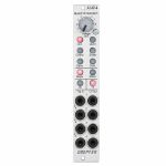
People also bought...
Doepfer A-149-4 Quad VC Random Polyphonic Random Voltage Source Slim Line Series Module (quad/random synth module)
Cat: 847089 Rel: 24 Jun 22 • View all Synth modules
Quad Random Voltage Source (Slim Line Series)
Notes: Module A-149-4 generates four triggered random voltages which meet the criteria choosen by several controls.
Manual controls for the criteria selection:
Octave range (manual control "Oct."): this parameter defines how many octaves are covered by the random voltages (0 ... +5V, with "Oct." control fully CCW only 0V are generated)
Grid (6 illuminated radio buttons): this parameter defines the grid of the random voltages:
Octaves (Oct)
Octaves + Quin (Quint)
Chords
Scale
Semitones
continuous (i.e. stepless)
Minor / Major (2 illuminated radio buttons): this parameter defines in case of chords or scales if they are minor or major. For all other grids this parameter has no meaning
Sixth / Seventh (2 illuminated separate buttons): these parameters defines if the sixth or seventh is added. Valid only if Oct, Quint, Chord or Scale is chosen as grid.
The output voltages follow the 1V/octave standard with exception of the Continuous mode. The voltages in this mode are totally random and do not follow the 1V/oct standard (i.e. not a multiple of 1/12V).
The generation of a new random voltage at the output (CV Out 1...4) is triggered by the corresponding trigger input (Trig. In 1...4). The trigger inputs are normalled top down. The minimum trigger level is +2.5V (up to max. +12V).
Applications:
random polyphonic structures (in combination with the polyphonic modules A-111-4, A-105-4, A-132-8, A-141-4 and e.g. A-157 as trigger source and A-173-1/2 for transposition of the polyphonic structures)
any application that requires several random voltages
Width: 4 HP / 20.0 mm
Depth: 45mm (measured from the rear side of the front panel)
… Read moreManual controls for the criteria selection:
Octave range (manual control "Oct."): this parameter defines how many octaves are covered by the random voltages (0 ... +5V, with "Oct." control fully CCW only 0V are generated)
Grid (6 illuminated radio buttons): this parameter defines the grid of the random voltages:
Octaves (Oct)
Octaves + Quin (Quint)
Chords
Scale
Semitones
continuous (i.e. stepless)
Minor / Major (2 illuminated radio buttons): this parameter defines in case of chords or scales if they are minor or major. For all other grids this parameter has no meaning
Sixth / Seventh (2 illuminated separate buttons): these parameters defines if the sixth or seventh is added. Valid only if Oct, Quint, Chord or Scale is chosen as grid.
The output voltages follow the 1V/octave standard with exception of the Continuous mode. The voltages in this mode are totally random and do not follow the 1V/oct standard (i.e. not a multiple of 1/12V).
The generation of a new random voltage at the output (CV Out 1...4) is triggered by the corresponding trigger input (Trig. In 1...4). The trigger inputs are normalled top down. The minimum trigger level is +2.5V (up to max. +12V).
Applications:
random polyphonic structures (in combination with the polyphonic modules A-111-4, A-105-4, A-132-8, A-141-4 and e.g. A-157 as trigger source and A-173-1/2 for transposition of the polyphonic structures)
any application that requires several random voltages
Width: 4 HP / 20.0 mm
Depth: 45mm (measured from the rear side of the front panel)
2 in stock $140.94
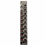
People also bought...
Doepfer A-160-2v Clock/Trigger Divider II Vintage Edition Module (black) (clock modulator/frequency divider synth module)
Cat: 864696 Rel: 14 Mar 22 • View all Synth modules
Module A-160-2 is an enhanced version of the standard clock divider A-160.
Notes: Module A-160-2V is an enhanced version of the standard clock divider A-160. The module is a frequency divider for clock/trigger/gate signals, designed to be a source of lower frequencies, particularly for rhythm uses.
The Clock input will take any digital signal from, eg., an LFO, MIDI sync, or the gate from a MIDI-CV interface. At the outputs, you have access to three sets of seven different sub-divided clock signals, from half the clock frequency down to 1/128. The low/high levels of the output signals are 0V and about +10V.
The A-160-2V also has a reset input. Whenever a reset signal is sensed, all outputs are set to certain levels which depend upon the selected mode.
HP : 4
… Read moreThe Clock input will take any digital signal from, eg., an LFO, MIDI sync, or the gate from a MIDI-CV interface. At the outputs, you have access to three sets of seven different sub-divided clock signals, from half the clock frequency down to 1/128. The low/high levels of the output signals are 0V and about +10V.
The A-160-2V also has a reset input. Whenever a reset signal is sensed, all outputs are set to certain levels which depend upon the selected mode.
HP : 4
5 in stock $107.83
Click for better price!
or call +44 20 7424 1960
quote 864696
quote 864696
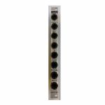
People also bought...
Doepfer A-126-2exp Voltage Controlled Frequency Shifter II - Expansion Module (silver) (expander synth module)
Cat: 852803 Rel: 04 Feb 22 • View all Synth modules
An expander for the A-126-2 Voltage Controlled Frequency Shifter.
Notes: The Doepfer A-126-2exp is an expander for the A-126-2 Voltage Controlled Frequency Shifter.
It adds two outputs from the Dome filter (+45 and -45 degrees) as well as separate outputs from the ring modulators 1 and 2, and from the internal envelope generator. Furthermore, it offers dedicated outputs for Up and Down Shift, allowing the module to be patched in stereo.
*Note: The expander can only be used in conjunction with the module A-126-2.
HP : 2
… Read moreIt adds two outputs from the Dome filter (+45 and -45 degrees) as well as separate outputs from the ring modulators 1 and 2, and from the internal envelope generator. Furthermore, it offers dedicated outputs for Up and Down Shift, allowing the module to be patched in stereo.
*Note: The expander can only be used in conjunction with the module A-126-2.
HP : 2
1 in stock $52.36
Click for better price!
or call +44 20 7424 1960
quote 852803
quote 852803
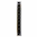
People also bought...
Doepfer A-126-2exp Voltage Controlled Frequency Shifter II - Expansion Vintage Edition Module (black) (expander synth module)
Cat: 852807 Rel: 04 Feb 22 • View all Synth modules
An expander for the A-126-2 Voltage Controlled Frequency Shifter.
Notes: The Doepfer A-126-2exp is an expander for the A-126-2 Voltage Controlled Frequency Shifter.
It adds two outputs from the Dome filter (+45 and -45 degrees) as well as separate outputs from the ring modulators 1 and 2, and from the internal envelope generator. Furthermore, it offers dedicated outputs for Up and Down Shift, allowing the module to be patched in stereo.
*Note: The expander can only be used in conjunction with the module A-126-2.
HP : 2
… Read moreIt adds two outputs from the Dome filter (+45 and -45 degrees) as well as separate outputs from the ring modulators 1 and 2, and from the internal envelope generator. Furthermore, it offers dedicated outputs for Up and Down Shift, allowing the module to be patched in stereo.
*Note: The expander can only be used in conjunction with the module A-126-2.
HP : 2
2 in stock $51.84
Click for better price!
or call +44 20 7424 1960
quote 852807
quote 852807
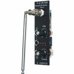
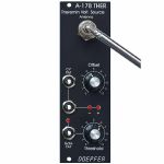
People also bought...
Doepfer A-178v Theremin Control Voltage Source Vintage Edition Module (black) (controller/CV modulation/utility synth module)
Cat: 852800 Rel: 05 Jan 22 • View all Synth modules
Theremin module for generating a variable control voltage by approaching/removing hand to/from an antenna.
Notes: Theremin module for generating a variable control voltage by approaching/removing hand to/from an antenna.
The distance range is about 30 cm. Additionally the module is equipped with a Gate output with adjustable threshold level. To simulate the original Theremin two A-178, a VCO (e.g. A-110) and a linear VCA (e.g. A-130 or A-132) are required. But of course the A-178 can be used to control other functions in the A-100 (e.g. filter frequency, modulation depth and/or speed, tempo, attack/decay time and so on).
The CV output voltage of the A-178 can range - according to the setting of the front panel controls - from -10V...+10V.
The gate output switches from 0V to about +10V.
Power consumption: 60mA at +12V and 20mA at -12V
Depth: 40mm
HP : 8
… Read moreThe distance range is about 30 cm. Additionally the module is equipped with a Gate output with adjustable threshold level. To simulate the original Theremin two A-178, a VCO (e.g. A-110) and a linear VCA (e.g. A-130 or A-132) are required. But of course the A-178 can be used to control other functions in the A-100 (e.g. filter frequency, modulation depth and/or speed, tempo, attack/decay time and so on).
The CV output voltage of the A-178 can range - according to the setting of the front panel controls - from -10V...+10V.
The gate output switches from 0V to about +10V.
Power consumption: 60mA at +12V and 20mA at -12V
Depth: 40mm
HP : 8
1 in stock $96.42
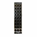
People also bought...
Doepfer A-130-8v Octal Linear VCA Vintage Edition Module (black) (mixer/quad/VCA synth module)
Cat: 852796 Rel: 16 Dec 21 • View all Synth modules
Octal Linear VCA / Voltage Controlled Mixers (Slim Line Series)
Notes: Module A-130-8 contains eight linear voltage controlled amplifiers (VCAs). Each VCA features a control voltage input (CV), a signal input (In) and a signal output (Out). In addition three mixers are included: the socket labelled "1-4" outputs the sum of the VCAs 1-4, the socket labelled "5-8" outputs the sum of the VCAs 5-8, the socket labelled "1-8" outputs the sum of all eight VCAs.
The signal inputs are able to process levels up to 10Vpp without clipping. Each CV input is equipped with a trimming potentiometer that is used to adjust the sensitivity of the CV input in question. In the factory the module is adjusted for the CV range 1...+5V but can be re-adjusted by the user for other control voltage ranges (e.g. 0...+10V).
The amplification range for each single VCA is 0...1. The signals of the sum outputs have a lower amplification to avoid distortion.
The VCAs and mixers are fully DC coupled, i.e. the module can be used for the processing of both audio and control voltage signals. The control voltage and signal inputs can be normalled by means of small solder pads (e.g. 1 > 2 > 3 > 4 and so on, or 1 > 5, 2 > 6, 3 > 7, 4 > 8 for the stereo application mentioned below).
Typical applications:
Any kind of VCA application (e.g. voltage controlled attenuation of audio or control voltage signals)
Two voltage controlled mixers with four channels each
Voltage controlled stereo mixer with four channels each, for this the control voltage inputs have to be correspondingly patched or internally normalled: CV1=CV5 / CV2=CV6 / CV3=CV7 / CV4=CV8
Voltage controlled mixer with eight channels
Add-on for the planned Joystick module A-174-4
Dimensions
6 HP
40 mm deep
Current Draw
50 mA +12V
50 mA -12V
0 mA 5V
… Read moreThe signal inputs are able to process levels up to 10Vpp without clipping. Each CV input is equipped with a trimming potentiometer that is used to adjust the sensitivity of the CV input in question. In the factory the module is adjusted for the CV range 1...+5V but can be re-adjusted by the user for other control voltage ranges (e.g. 0...+10V).
The amplification range for each single VCA is 0...1. The signals of the sum outputs have a lower amplification to avoid distortion.
The VCAs and mixers are fully DC coupled, i.e. the module can be used for the processing of both audio and control voltage signals. The control voltage and signal inputs can be normalled by means of small solder pads (e.g. 1 > 2 > 3 > 4 and so on, or 1 > 5, 2 > 6, 3 > 7, 4 > 8 for the stereo application mentioned below).
Typical applications:
Any kind of VCA application (e.g. voltage controlled attenuation of audio or control voltage signals)
Two voltage controlled mixers with four channels each
Voltage controlled stereo mixer with four channels each, for this the control voltage inputs have to be correspondingly patched or internally normalled: CV1=CV5 / CV2=CV6 / CV3=CV7 / CV4=CV8
Voltage controlled mixer with eight channels
Add-on for the planned Joystick module A-174-4
Dimensions
6 HP
40 mm deep
Current Draw
50 mA +12V
50 mA -12V
0 mA 5V
1 in stock $121.31
Click for better price!
or call +44 20 7424 1960
quote 852796
quote 852796
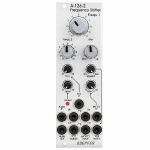
People also bought...
Doepfer A-126-2 Frequency Shifter Eurorack Module (eurorack oscillator/phase shifter/pitch shifter/VCA module)
Cat: 847081 Rel: 17 Nov 21 • View all Synth modules
Voltage Controlled Frequency Shifter II
Notes: Module A-126-2 is a fully analog frequency shifter for audio signals. A frequency shifter is an audio processing unit that shifts each frequency of the incoming audio signal by the same frequency. If the shifting frequency is e.g. 200Hz an incoming audio frequency of 1000 Hz becomes 1200 Hz, 2000Hz becomes 2200 Hz, 3000 Hz becomes 3200 Hz and so on. Pay attention that this is different from pitch shifting where all frequencies are shifted proportional (e.g. 1000>1200Hz, 2000>2400Hz, 3000>3600Hz) !
The frequency range of the internal quadrature VCO is about 8 octaves (about 20Hz ... 5kHz). If required an external quadrature VCO can be used.
The module is equipped with these controls, inputs and outputs:
Frequ. 1: first manual control of the shifting frequency (factory setting: coarse, range about 20Hz - 5 kHz)
Frequ. 2: second manual control of the shifting frequency (factory setting: fine)
by means of internal jumpers the sensitivity of Frequ.1 and 2 can be swapped (i.e. Frequ.1 = fine and Frequ.2 = coarse)
the relation between coarse and fine control is about 25:1 (corresponding to about 8 octaves to 1/3 octave)
FCV In (socket) and FCV (small control without knob): control voltage input with attenuator for the external voltage control of the shifting frequency
Mix: manual control of the up/down shift panning unit, fully CCW = down shift, fully CW = up shift, in between a mixture of down and up
Mix CV In (socket) and Mix CV (small control without knob): control voltage input with attenuator for the mixing unit for external voltage control of the up/down mixing
Audio In (socket), Level (small control without knob) and Overload (LED): audio input with attenuator, typ. audio in level = 1Vpp, the level control has to be adjusted so that the overload LED just begins to light up a bit, when the LED is fully on clipping/distortion occurs, when the LED is permanently off the input level is too low and the signal-to-noise ratio increases
Audio Out (socket): audio output of the frequency shifter
Squelch (small control without knob): controls the squelch function: fully CCW (Env.) the output VCA is controlled by the envelope signal, which is derived from the audio input signal, fully CW (open) the output VCA is permanently open (no squelch function), in between the squelch intensity can be adjusted
Quadrature VCO Outputs (sockets Sin and Cos): outputs of the internal quadrature oscillator, about 12Vpp level (+6V/-6V)
Ext. Inputs Sin and Cos (sockets): required when an external quadrature VCO (e.g. A-143-9 with a wider frequency range or A-110-4 with thru zero feature or A-110-6 with different waveforms) is used instead of the internal quadrature VCO, the levels of the external VCO should be about 10Vpp (8...10Vpp are OK) and the signals have to be symmetrical around zero Volts, the sockets are normalled to the internal quadrature VCO (i.e. the sockets are equipped with switching contacts that interrupt the internal connection as soon as a plug inserted)
VCA ext. CV (socket): used when an external control voltage (e.g. from an envelope generator) should be used to control the output VCA instead of the internal squelch unit, the socket is normalled to the output of the squelch control (i.e. the socket is equipped with a switching contact that interrupts the internal squelch connection as soon as a plug inserted). From about +8V external control voltage the VCA is fully open.
Internal terminals (pin headers, e.g. for a DIY breakout module):
envelope follower output
dome filter output 1
dome filter output 2
ring modulator 1 output
ring modulator 2 output
Up shift output
Down shift output
… Read moreThe frequency range of the internal quadrature VCO is about 8 octaves (about 20Hz ... 5kHz). If required an external quadrature VCO can be used.
The module is equipped with these controls, inputs and outputs:
Frequ. 1: first manual control of the shifting frequency (factory setting: coarse, range about 20Hz - 5 kHz)
Frequ. 2: second manual control of the shifting frequency (factory setting: fine)
by means of internal jumpers the sensitivity of Frequ.1 and 2 can be swapped (i.e. Frequ.1 = fine and Frequ.2 = coarse)
the relation between coarse and fine control is about 25:1 (corresponding to about 8 octaves to 1/3 octave)
FCV In (socket) and FCV (small control without knob): control voltage input with attenuator for the external voltage control of the shifting frequency
Mix: manual control of the up/down shift panning unit, fully CCW = down shift, fully CW = up shift, in between a mixture of down and up
Mix CV In (socket) and Mix CV (small control without knob): control voltage input with attenuator for the mixing unit for external voltage control of the up/down mixing
Audio In (socket), Level (small control without knob) and Overload (LED): audio input with attenuator, typ. audio in level = 1Vpp, the level control has to be adjusted so that the overload LED just begins to light up a bit, when the LED is fully on clipping/distortion occurs, when the LED is permanently off the input level is too low and the signal-to-noise ratio increases
Audio Out (socket): audio output of the frequency shifter
Squelch (small control without knob): controls the squelch function: fully CCW (Env.) the output VCA is controlled by the envelope signal, which is derived from the audio input signal, fully CW (open) the output VCA is permanently open (no squelch function), in between the squelch intensity can be adjusted
Quadrature VCO Outputs (sockets Sin and Cos): outputs of the internal quadrature oscillator, about 12Vpp level (+6V/-6V)
Ext. Inputs Sin and Cos (sockets): required when an external quadrature VCO (e.g. A-143-9 with a wider frequency range or A-110-4 with thru zero feature or A-110-6 with different waveforms) is used instead of the internal quadrature VCO, the levels of the external VCO should be about 10Vpp (8...10Vpp are OK) and the signals have to be symmetrical around zero Volts, the sockets are normalled to the internal quadrature VCO (i.e. the sockets are equipped with switching contacts that interrupt the internal connection as soon as a plug inserted)
VCA ext. CV (socket): used when an external control voltage (e.g. from an envelope generator) should be used to control the output VCA instead of the internal squelch unit, the socket is normalled to the output of the squelch control (i.e. the socket is equipped with a switching contact that interrupts the internal squelch connection as soon as a plug inserted). From about +8V external control voltage the VCA is fully open.
Internal terminals (pin headers, e.g. for a DIY breakout module):
envelope follower output
dome filter output 1
dome filter output 2
ring modulator 1 output
ring modulator 2 output
Up shift output
Down shift output
1 in stock $322.47
Click for better price!
or call +44 20 7424 1960
quote 847081
quote 847081
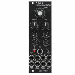
People also bought...
Doepfer A-126-2v Frequency Shifter Vintage Edition Module (black) (oscillator/phase shifter/pitch shifter/VCA synth module)
Cat: 847083 Rel: 17 Nov 21 • View all Synth modules
Voltage Controlled Frequency Shifter II
Notes: 'Vintage' black panel version of Doepfer's updated frequency shifter module, offering weird and wonderful effects by shifting all frequencies by a fixed amount. Unique sound, not to be confused with pitch shifting.
Supplier's Notes:
Module A-126-2 is a fully analog frequency shifter for audio signals. A frequency shifter is an audio processing unit that shifts each frequency of the incoming audio signal by the same frequency. If the shifting frequency is e.g. 200Hz an incoming audio frequency of 1000 Hz becomes 1200 Hz, 2000Hz becomes 2200 Hz, 3000 Hz becomes 3200 Hz and so on. Pay attention that this is different from pitch shifting where all frequencies are shifted proportional (e.g. 1000>1200Hz, 2000>2400Hz, 3000>3600Hz) !
The frequency range of the internal quadrature VCO is about 8 octaves (about 20Hz ... 5kHz). If required an external quadrature VCO can be used.
The module is equipped with these controls, inputs and outputs:
Frequ. 1: first manual control of the shifting frequency (factory setting: coarse, range about 20Hz - 5 kHz)
Frequ. 2: second manual control of the shifting frequency (factory setting: fine)
by means of internal jumpers the sensitivity of Frequ.1 and 2 can be swapped (i.e. Frequ.1 = fine and Frequ.2 = coarse)
the relation between coarse and fine control is about 25:1 (corresponding to about 8 octaves to 1/3 octave)
FCV In (socket) and FCV (small control without knob): control voltage input with attenuator for the external voltage control of the shifting frequency
Mix: manual control of the up/down shift panning unit, fully CCW = down shift, fully CW = up shift, in between a mixture of down and up
Mix CV In (socket) and Mix CV (small control without knob): control voltage input with attenuator for the mixing unit for external voltage control of the up/down mixing
Audio In (socket), Level (small control without knob) and Overload (LED): audio input with attenuator, typ. audio in level = 1Vpp, the level control has to be adjusted so that the overload LED just begins to light up a bit, when the LED is fully on clipping/distortion occurs, when the LED is permanently off the input level is too low and the signal-to-noise ratio increases
Audio Out (socket): audio output of the frequency shifter
Squelch (small control without knob): controls the squelch function: fully CCW (Env.) the output VCA is controlled by the envelope signal, which is derived from the audio input signal, fully CW (open) the output VCA is permanently open (no squelch function), in between the squelch intensity can be adjusted
Quadrature VCO Outputs (sockets Sin and Cos): outputs of the internal quadrature oscillator, about 12Vpp level (+6V/-6V)
Ext. Inputs Sin and Cos (sockets): required when an external quadrature VCO (e.g. A-143-9 with a wider frequency range or A-110-4 with thru zero feature or A-110-6 with different waveforms) is used instead of the internal quadrature VCO, the levels of the external VCO should be about 10Vpp (8...10Vpp are OK) and the signals have to be symmetrical around zero Volts, the sockets are normalled to the internal quadrature VCO (i.e. the sockets are equipped with switching contacts that interrupt the internal connection as soon as a plug inserted)
VCA ext. CV (socket): used when an external control voltage (e.g. from an envelope generator) should be used to control the output VCA instead of the internal squelch unit, the socket is normalled to the output of the squelch control (i.e. the socket is equipped with a switching contact that interrupts the internal squelch connection as soon as a plug inserted). From about +8V external control voltage the VCA is fully open.
Internal terminals (pin headers, e.g. for a DIY breakout module):
envelope follower output
dome filter output 1
dome filter output 2
ring modulator 1 output
ring modulator 2 output
Up shift output
Down shift output
… Read moreSupplier's Notes:
Module A-126-2 is a fully analog frequency shifter for audio signals. A frequency shifter is an audio processing unit that shifts each frequency of the incoming audio signal by the same frequency. If the shifting frequency is e.g. 200Hz an incoming audio frequency of 1000 Hz becomes 1200 Hz, 2000Hz becomes 2200 Hz, 3000 Hz becomes 3200 Hz and so on. Pay attention that this is different from pitch shifting where all frequencies are shifted proportional (e.g. 1000>1200Hz, 2000>2400Hz, 3000>3600Hz) !
The frequency range of the internal quadrature VCO is about 8 octaves (about 20Hz ... 5kHz). If required an external quadrature VCO can be used.
The module is equipped with these controls, inputs and outputs:
Frequ. 1: first manual control of the shifting frequency (factory setting: coarse, range about 20Hz - 5 kHz)
Frequ. 2: second manual control of the shifting frequency (factory setting: fine)
by means of internal jumpers the sensitivity of Frequ.1 and 2 can be swapped (i.e. Frequ.1 = fine and Frequ.2 = coarse)
the relation between coarse and fine control is about 25:1 (corresponding to about 8 octaves to 1/3 octave)
FCV In (socket) and FCV (small control without knob): control voltage input with attenuator for the external voltage control of the shifting frequency
Mix: manual control of the up/down shift panning unit, fully CCW = down shift, fully CW = up shift, in between a mixture of down and up
Mix CV In (socket) and Mix CV (small control without knob): control voltage input with attenuator for the mixing unit for external voltage control of the up/down mixing
Audio In (socket), Level (small control without knob) and Overload (LED): audio input with attenuator, typ. audio in level = 1Vpp, the level control has to be adjusted so that the overload LED just begins to light up a bit, when the LED is fully on clipping/distortion occurs, when the LED is permanently off the input level is too low and the signal-to-noise ratio increases
Audio Out (socket): audio output of the frequency shifter
Squelch (small control without knob): controls the squelch function: fully CCW (Env.) the output VCA is controlled by the envelope signal, which is derived from the audio input signal, fully CW (open) the output VCA is permanently open (no squelch function), in between the squelch intensity can be adjusted
Quadrature VCO Outputs (sockets Sin and Cos): outputs of the internal quadrature oscillator, about 12Vpp level (+6V/-6V)
Ext. Inputs Sin and Cos (sockets): required when an external quadrature VCO (e.g. A-143-9 with a wider frequency range or A-110-4 with thru zero feature or A-110-6 with different waveforms) is used instead of the internal quadrature VCO, the levels of the external VCO should be about 10Vpp (8...10Vpp are OK) and the signals have to be symmetrical around zero Volts, the sockets are normalled to the internal quadrature VCO (i.e. the sockets are equipped with switching contacts that interrupt the internal connection as soon as a plug inserted)
VCA ext. CV (socket): used when an external control voltage (e.g. from an envelope generator) should be used to control the output VCA instead of the internal squelch unit, the socket is normalled to the output of the squelch control (i.e. the socket is equipped with a switching contact that interrupts the internal squelch connection as soon as a plug inserted). From about +8V external control voltage the VCA is fully open.
Internal terminals (pin headers, e.g. for a DIY breakout module):
envelope follower output
dome filter output 1
dome filter output 2
ring modulator 1 output
ring modulator 2 output
Up shift output
Down shift output
2 in stock $324.35

People also bought...
Doepfer A-182-4 Dual Rotary Switches Slim Line Series Module (dual/stereo/switch module)
Cat: 847091 Rel: 17 Nov 21 • View all Synth modules
Dual rotary switches module - 4HP
Notes: Module A-182-4 is a simple passive module that contains two mechanical rotary switches with 4 positions each. According to the position of the control knob socket 1, 2, 3 or 4 is connected to the common socket C.
As the module is fully passive it works bidirectional, i.e. the sockets 1...4 can be inputs and then C is the output. The other way round C can be the input and the sockets 1...4 are the outputs.
By means of an internal jumper the terminals C of both switches can be connected. That way the module can be used as kind of a miniature 4x4 matrix. Rotary switch A is e.g. used to select one of the four sockets 1...4 as input and this signal is sent to one of the four sockets 1...4 of switch B.
Applications:
switching of audio or control signals in the modular system without the need to unplug and plug patch cables (i.e. no signal interruptions)
building a small 4x4 miniature switch matrix
Width: 4 HP / 20.0 mm
Depth: 20mm (measured from the rear side of the front panel)
Current: 0mA (+12V) / 0mA (-12V)
… Read moreAs the module is fully passive it works bidirectional, i.e. the sockets 1...4 can be inputs and then C is the output. The other way round C can be the input and the sockets 1...4 are the outputs.
By means of an internal jumper the terminals C of both switches can be connected. That way the module can be used as kind of a miniature 4x4 matrix. Rotary switch A is e.g. used to select one of the four sockets 1...4 as input and this signal is sent to one of the four sockets 1...4 of switch B.
Applications:
switching of audio or control signals in the modular system without the need to unplug and plug patch cables (i.e. no signal interruptions)
building a small 4x4 miniature switch matrix
Width: 4 HP / 20.0 mm
Depth: 20mm (measured from the rear side of the front panel)
Current: 0mA (+12V) / 0mA (-12V)
out of stock $61.17

People also bought...
Doepfer A-126-2v Frequency Shifter Vintage Edition Module (black) (B-STOCK) (oscillator/phase shifter/pitch shifter/VCA synth module)
Cat: 912589 Rel: 17 Nov 21 • View all Synth modules
B-STOCK: Item refurbished, repaired and in perfect working order.
Notes: ***B-STOCK: Item refurbished, repaired and in perfect working order.***
'Vintage' black panel version of Doepfer's updated frequency shifter module, offering weird and wonderful effects by shifting all frequencies by a fixed amount. Unique sound, not to be confused with pitch shifting.
Supplier's Notes:
Module A-126-2 is a fully analog frequency shifter for audio signals. A frequency shifter is an audio processing unit that shifts each frequency of the incoming audio signal by the same frequency. If the shifting frequency is e.g. 200Hz an incoming audio frequency of 1000 Hz becomes 1200 Hz, 2000Hz becomes 2200 Hz, 3000 Hz becomes 3200 Hz and so on. Pay attention that this is different from pitch shifting where all frequencies are shifted proportional (e.g. 1000>1200Hz, 2000>2400Hz, 3000>3600Hz) !
The frequency range of the internal quadrature VCO is about 8 octaves (about 20Hz ... 5kHz). If required an external quadrature VCO can be used.
The module is equipped with these controls, inputs and outputs:
Frequ. 1: first manual control of the shifting frequency (factory setting: coarse, range about 20Hz - 5 kHz)
Frequ. 2: second manual control of the shifting frequency (factory setting: fine)
by means of internal jumpers the sensitivity of Frequ.1 and 2 can be swapped (i.e. Frequ.1 = fine and Frequ.2 = coarse)
the relation between coarse and fine control is about 25:1 (corresponding to about 8 octaves to 1/3 octave)
FCV In (socket) and FCV (small control without knob): control voltage input with attenuator for the external voltage control of the shifting frequency
Mix: manual control of the up/down shift panning unit, fully CCW = down shift, fully CW = up shift, in between a mixture of down and up
Mix CV In (socket) and Mix CV (small control without knob): control voltage input with attenuator for the mixing unit for external voltage control of the up/down mixing
Audio In (socket), Level (small control without knob) and Overload (LED): audio input with attenuator, typ. audio in level = 1Vpp, the level control has to be adjusted so that the overload LED just begins to light up a bit, when the LED is fully on clipping/distortion occurs, when the LED is permanently off the input level is too low and the signal-to-noise ratio increases
Audio Out (socket): audio output of the frequency shifter
Squelch (small control without knob): controls the squelch function: fully CCW (Env.) the output VCA is controlled by the envelope signal, which is derived from the audio input signal, fully CW (open) the output VCA is permanently open (no squelch function), in between the squelch intensity can be adjusted
Quadrature VCO Outputs (sockets Sin and Cos): outputs of the internal quadrature oscillator, about 12Vpp level (+6V/-6V)
Ext. Inputs Sin and Cos (sockets): required when an external quadrature VCO (e.g. A-143-9 with a wider frequency range or A-110-4 with thru zero feature or A-110-6 with different waveforms) is used instead of the internal quadrature VCO, the levels of the external VCO should be about 10Vpp (8...10Vpp are OK) and the signals have to be symmetrical around zero Volts, the sockets are normalled to the internal quadrature VCO (i.e. the sockets are equipped with switching contacts that interrupt the internal connection as soon as a plug inserted)
VCA ext. CV (socket): used when an external control voltage (e.g. from an envelope generator) should be used to control the output VCA instead of the internal squelch unit, the socket is normalled to the output of the squelch control (i.e. the socket is equipped with a switching contact that interrupts the internal squelch connection as soon as a plug inserted). From about +8V external control voltage the VCA is fully open.
Internal terminals (pin headers, e.g. for a DIY breakout module):
envelope follower output
dome filter output 1
dome filter output 2
ring modulator 1 output
ring modulator 2 output
Up shift output
Down shift output
… Read more'Vintage' black panel version of Doepfer's updated frequency shifter module, offering weird and wonderful effects by shifting all frequencies by a fixed amount. Unique sound, not to be confused with pitch shifting.
Supplier's Notes:
Module A-126-2 is a fully analog frequency shifter for audio signals. A frequency shifter is an audio processing unit that shifts each frequency of the incoming audio signal by the same frequency. If the shifting frequency is e.g. 200Hz an incoming audio frequency of 1000 Hz becomes 1200 Hz, 2000Hz becomes 2200 Hz, 3000 Hz becomes 3200 Hz and so on. Pay attention that this is different from pitch shifting where all frequencies are shifted proportional (e.g. 1000>1200Hz, 2000>2400Hz, 3000>3600Hz) !
The frequency range of the internal quadrature VCO is about 8 octaves (about 20Hz ... 5kHz). If required an external quadrature VCO can be used.
The module is equipped with these controls, inputs and outputs:
Frequ. 1: first manual control of the shifting frequency (factory setting: coarse, range about 20Hz - 5 kHz)
Frequ. 2: second manual control of the shifting frequency (factory setting: fine)
by means of internal jumpers the sensitivity of Frequ.1 and 2 can be swapped (i.e. Frequ.1 = fine and Frequ.2 = coarse)
the relation between coarse and fine control is about 25:1 (corresponding to about 8 octaves to 1/3 octave)
FCV In (socket) and FCV (small control without knob): control voltage input with attenuator for the external voltage control of the shifting frequency
Mix: manual control of the up/down shift panning unit, fully CCW = down shift, fully CW = up shift, in between a mixture of down and up
Mix CV In (socket) and Mix CV (small control without knob): control voltage input with attenuator for the mixing unit for external voltage control of the up/down mixing
Audio In (socket), Level (small control without knob) and Overload (LED): audio input with attenuator, typ. audio in level = 1Vpp, the level control has to be adjusted so that the overload LED just begins to light up a bit, when the LED is fully on clipping/distortion occurs, when the LED is permanently off the input level is too low and the signal-to-noise ratio increases
Audio Out (socket): audio output of the frequency shifter
Squelch (small control without knob): controls the squelch function: fully CCW (Env.) the output VCA is controlled by the envelope signal, which is derived from the audio input signal, fully CW (open) the output VCA is permanently open (no squelch function), in between the squelch intensity can be adjusted
Quadrature VCO Outputs (sockets Sin and Cos): outputs of the internal quadrature oscillator, about 12Vpp level (+6V/-6V)
Ext. Inputs Sin and Cos (sockets): required when an external quadrature VCO (e.g. A-143-9 with a wider frequency range or A-110-4 with thru zero feature or A-110-6 with different waveforms) is used instead of the internal quadrature VCO, the levels of the external VCO should be about 10Vpp (8...10Vpp are OK) and the signals have to be symmetrical around zero Volts, the sockets are normalled to the internal quadrature VCO (i.e. the sockets are equipped with switching contacts that interrupt the internal connection as soon as a plug inserted)
VCA ext. CV (socket): used when an external control voltage (e.g. from an envelope generator) should be used to control the output VCA instead of the internal squelch unit, the socket is normalled to the output of the squelch control (i.e. the socket is equipped with a switching contact that interrupts the internal squelch connection as soon as a plug inserted). From about +8V external control voltage the VCA is fully open.
Internal terminals (pin headers, e.g. for a DIY breakout module):
envelope follower output
dome filter output 1
dome filter output 2
ring modulator 1 output
ring modulator 2 output
Up shift output
Down shift output
out of stock $292.73

People also bought...
Doepfer A-138f Dual 3-Way Crossfader Slim Line Series Module (silver) (dual/stereo/mixer/panning synth module)
Cat: 847088 Rel: 09 Nov 21 • View all Synth modules
Dual Three-Way Crossfader (Slim Line Series)
Notes: Module A-138f contains two identical crossfaders with three inputs and one output each. Three different signals are connected to the inputs A, B and C. In the ccw position of the corresponding control only signal A appears at the output. Between ccw and center position a mix of the signals A and B appears at the output. In the center position only signal B appears at the output. Between center and cw position a mix of signals B and C appears at the output. In the cw position only signal C appears at the output.
The module is DC coupled and can be used for both audio and control voltage processing.
Application examples:
Crossfading of VCO waveforms (e.g. saw - rectangle - triangle)
Crossfading of VCF outputs of multimode filters (e.g. lowpass - notch - highpass - bandpass)
Crossfading of control voltage signals (e.g. envelope - LFO - random)
Width: 4 HP / 20.0 mm
Depth: 30 mm (measured from the rear side of the front panel)
Current: +10mA (+12V) / -10mA (-12V)
… Read moreThe module is DC coupled and can be used for both audio and control voltage processing.
Application examples:
Crossfading of VCO waveforms (e.g. saw - rectangle - triangle)
Crossfading of VCF outputs of multimode filters (e.g. lowpass - notch - highpass - bandpass)
Crossfading of control voltage signals (e.g. envelope - LFO - random)
Width: 4 HP / 20.0 mm
Depth: 30 mm (measured from the rear side of the front panel)
Current: +10mA (+12V) / -10mA (-12V)
out of stock $64.29
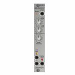
People also bought...
Doepfer A-179-2 Light Controlled Voltage Source II Slim Line Series Module (silver) (controller synth module)
Cat: 847090 Rel: 09 Nov 21 • View all Synth modules
Light Controlled Voltage Source II (Slim Line Series)
Notes: Module A-179-2 can be used to convert different illumination intensities into corresponding analog voltages and a gate signal derived from the analog voltage. It's the successor of the obsolete module A-179.
A light sensitive resistor (LDR) converts the illumination of the internal light sensor into a corresponding analog control voltage. The internal sensor is located at the front panel. Instead of the internal sensor a remote sensor can be connected via a standard patch cable to the module (ext.Sens. socket). An external sensor with a 2 m patch cable (A-100C200) is included. The external sensor is mounted on a small pc board which is equipped also with a 3.5 mm jack socket. The nut of the socket can also be used to mount the external sensor.
The module A-179 is similar to the Theremin module A-178 but uses the illumination intensity instead of the distance between hand and antenna for generating the analog voltage.
One can choose between passive control by covering/shading the sensor via hand or body, or active control by using e.g. a pocket lamp or flashlight. For this two versions of output voltages are available (CV Out + und CV Out -).
The module has these controls and in/outputs available:
ext. Sens.: by means of a standard patch cable the external sensor can be connected to this socket. In this case the internal sensor is turned off.
CV Offset: control to adjust the output voltage which is assigned to a certain illumination (e.g. 0V for complete darkness)
CV Level: control that is used to adjust the sensitivity of the generated output voltage (i.e. how much a certain difference in brightness affects the output voltage)
Gate Threshold: control that is used to adjust the threshold for the generation of the gate signal, an internal jumper is used to define if the gate signal is derived from the CV Out+ or CV Out- voltage.
CV Out+: positive control voltage output, increasing brighness causes the increase of the voltage at this output
CV Out+: negative control voltage output, increasing brighness causes the decrease of the voltage at this output
LED CV Out: bipolar LED (red/yellow) as display for the CV outputs
Gate: gate output with LED display
Applications:
controlling any voltage controlled parameter e.g. pitch or pulswidth of a VCO, filter frequency or resonance of a VCF, loudness of a VCA, time of an envelope generator, frequency of a VCLFO
triggering activities via gate with adjustable threshold, e.g. starting an envelope, starting/stopping a sequencer or any switching function (e.g. with A-150-1 or 151).
Conversion into MIDI control change messages is possible with the A-192-2.
Width: 4 HP / 20.0 mm
Depth: 30mm (measured from the rear side of the front panel)
… Read moreA light sensitive resistor (LDR) converts the illumination of the internal light sensor into a corresponding analog control voltage. The internal sensor is located at the front panel. Instead of the internal sensor a remote sensor can be connected via a standard patch cable to the module (ext.Sens. socket). An external sensor with a 2 m patch cable (A-100C200) is included. The external sensor is mounted on a small pc board which is equipped also with a 3.5 mm jack socket. The nut of the socket can also be used to mount the external sensor.
The module A-179 is similar to the Theremin module A-178 but uses the illumination intensity instead of the distance between hand and antenna for generating the analog voltage.
One can choose between passive control by covering/shading the sensor via hand or body, or active control by using e.g. a pocket lamp or flashlight. For this two versions of output voltages are available (CV Out + und CV Out -).
The module has these controls and in/outputs available:
ext. Sens.: by means of a standard patch cable the external sensor can be connected to this socket. In this case the internal sensor is turned off.
CV Offset: control to adjust the output voltage which is assigned to a certain illumination (e.g. 0V for complete darkness)
CV Level: control that is used to adjust the sensitivity of the generated output voltage (i.e. how much a certain difference in brightness affects the output voltage)
Gate Threshold: control that is used to adjust the threshold for the generation of the gate signal, an internal jumper is used to define if the gate signal is derived from the CV Out+ or CV Out- voltage.
CV Out+: positive control voltage output, increasing brighness causes the increase of the voltage at this output
CV Out+: negative control voltage output, increasing brighness causes the decrease of the voltage at this output
LED CV Out: bipolar LED (red/yellow) as display for the CV outputs
Gate: gate output with LED display
Applications:
controlling any voltage controlled parameter e.g. pitch or pulswidth of a VCO, filter frequency or resonance of a VCF, loudness of a VCA, time of an envelope generator, frequency of a VCLFO
triggering activities via gate with adjustable threshold, e.g. starting an envelope, starting/stopping a sequencer or any switching function (e.g. with A-150-1 or 151).
Conversion into MIDI control change messages is possible with the A-192-2.
Width: 4 HP / 20.0 mm
Depth: 30mm (measured from the rear side of the front panel)
1 in stock $70.50
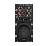
People also bought...
Doepfer A-174-4V 3D Joystick Vintage Edition Module (black) (controller/CV modulation synth module)
Cat: 805667 Rel: 17 Feb 21 • View all Synth modules
Vintage edition of Doepfer A-174 4 joystick module
Notes: Module A-174-4 outputs three control voltages generated by a spring-loaded X/Y cross potentiometer (so-called joy stick) and a Gate signal. The control voltages for X and Y are controlled by the X and Y position of the joystick in the usual way. The third control voltage Z is controlled by the rotation of the spring-loaded joystick knob. The Gate signal is generated by a button at the center/top of the joystick knob.
For each control voltage the non-inverted signal (X, Y, Z) as well as the inverted signal with adjustable offset (-X+XO, -Y+YO, -Z+ZO) are available. The generic joystick control voltages are bipolar, i.e. they range from typ. -5V (lowest position) via 0V (center position) to typ. +5V (highest position). The "Overlap" switches can be used to add a fixed offset voltage of typ. +5V to the non-inverting output in question so that the output voltage range changes to typ. 0...+10V (rather than -5...+5V). That's necessary if e.g. a VCA has to be controlled, which requires a pure positive control voltage range. The switches are named "overlap" because they allow the overlapping of the non-inverting CV output (X, Y, Z) with the inverting output (-X+XO, -Y+YO, -Z+ZO) for crossfading applications. With the overlap switch "on" and appropriate setting of the offset control it's possible to obtain a control voltage range of 0...+10V for the non-inverting output and +10V...0V (i.e. same range but opposite direction) for the inverting output.
The offset voltages which are added to the inverting outputs can be adjusted by means of three small potentiometers. That way different kinds of control voltage ranges are possible, e.g.
-5V ... +5V for the non-inverting output and +5V ... -5V for the inverting output ( Overlap = off, Offset = 0)
0 ... +10V for the non-inverting output and +10V ... 0V for the inverting output ( Overlap = on, Offset = max)
-5V ... +5V for the non-inverting output and +10V ... 0V for the inverting output ( Overlap = off, Offset = max)
0 ... +10V for the non-inverting output and +5V ... -5V for the inverting output ( Overlap = on, Offset = 0)
On top of this the four quadrant voltages Q1, Q2, Q3 and Q4 are available. A quadrant voltage becomes positive when the joystick is positioned in the quadrant in question.
Each CV output is equipped with an LED that displays the present voltage.
Important note:
Because of the construction height of the joystick (about 7 cm) the module cannot be installed into the cases A-100P6, A-100P9, A-100PMS6, A-100PMS9 and A-100PMS12 during transportation as the depth of the case cover is not sufficient. Into the base cases A-100PB and A-100PMB as well as in all other cases without cover the module can be installed without problems. Doepfer are close to finding a solution for this problem.
HP : 12
… Read moreFor each control voltage the non-inverted signal (X, Y, Z) as well as the inverted signal with adjustable offset (-X+XO, -Y+YO, -Z+ZO) are available. The generic joystick control voltages are bipolar, i.e. they range from typ. -5V (lowest position) via 0V (center position) to typ. +5V (highest position). The "Overlap" switches can be used to add a fixed offset voltage of typ. +5V to the non-inverting output in question so that the output voltage range changes to typ. 0...+10V (rather than -5...+5V). That's necessary if e.g. a VCA has to be controlled, which requires a pure positive control voltage range. The switches are named "overlap" because they allow the overlapping of the non-inverting CV output (X, Y, Z) with the inverting output (-X+XO, -Y+YO, -Z+ZO) for crossfading applications. With the overlap switch "on" and appropriate setting of the offset control it's possible to obtain a control voltage range of 0...+10V for the non-inverting output and +10V...0V (i.e. same range but opposite direction) for the inverting output.
The offset voltages which are added to the inverting outputs can be adjusted by means of three small potentiometers. That way different kinds of control voltage ranges are possible, e.g.
-5V ... +5V for the non-inverting output and +5V ... -5V for the inverting output ( Overlap = off, Offset = 0)
0 ... +10V for the non-inverting output and +10V ... 0V for the inverting output ( Overlap = on, Offset = max)
-5V ... +5V for the non-inverting output and +10V ... 0V for the inverting output ( Overlap = off, Offset = max)
0 ... +10V for the non-inverting output and +5V ... -5V for the inverting output ( Overlap = on, Offset = 0)
On top of this the four quadrant voltages Q1, Q2, Q3 and Q4 are available. A quadrant voltage becomes positive when the joystick is positioned in the quadrant in question.
Each CV output is equipped with an LED that displays the present voltage.
Important note:
Because of the construction height of the joystick (about 7 cm) the module cannot be installed into the cases A-100P6, A-100P9, A-100PMS6, A-100PMS9 and A-100PMS12 during transportation as the depth of the case cover is not sufficient. Into the base cases A-100PB and A-100PMB as well as in all other cases without cover the module can be installed without problems. Doepfer are close to finding a solution for this problem.
HP : 12
out of stock $175.23
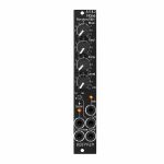
People also bought...
Doepfer A-118-2V Noise/Random/Sample & Hold Vintage Edition Module (black) (noise/random/sample & hold synth module)
Cat: 790467 Rel: 10 Nov 20 • View all Synth modules
Signal generator module
Notes: Module A-118-2 generates the signals white noise, colored noise, continuous random voltage and stepped random voltage.
The noise signal is generated 100% analog by amplification of the noise of a transistor. White and colored noise are usually used as audio sources. The random voltages are normally used as control voltages (e.g. for filter frequency or any other voltage controlled parameter).
The A-118-2 gives you the ability to mix the relative amounts of Red and Blue noise (low/high frequency component) in the colored noise output.
For the continuous random voltage the rate of change (Rate) and amplitude (Level) of the random voltage can be adjusted. The continuous random voltage is used as source for the S&H/T&H unit. The type of operation can be set to S&H (sample and hold) or T&H (track and hold). When T&H is chosen the output signal follows the input signal as long as the Clock input is "high". As soon as the clock signal changes to "low" the last voltage is stored. When S&H is chosen the input signal is sampled at the rising edge of the Clock signal. For the Clock signal a "digital" signal (e.g. Clock, Gate, rectangle output of an LFO) is required. Dual color LEDs are used to indicates the continuous and stepped random voltages.
Controls:
Blue: share of the high frequencies in the the colored noise output
Red: share of the low frequencies in the the colored noise output
Rate: rate of change of the continuous random voltage
Level: amplitude of the continuous random voltage
TH/SH: switches between T&H und S&H
Inputs and outputs:
RND: continuous random voltage output (with LED display)
TH/SH: stepped random voltage output (with LED display)
Clk: Clock input of the S&H/T&H unit
C Noise: colored noise output
W Noise: white noise output
Important notes:
After power on it takes a few minutes until the two noise signals and the random signals are generated. The module is not faulty when after power on the signals do not appear immediately!
The S&H/T&H function is realized by pure analog circuitry (electronic switch followed by a holding capacitor and buffer). Consequently the output voltage drifts a bit in the holding state because the capacitor is discharged by parasitic resistors. The drift depends also upon environmental conditions like humidity or temperature.
The level of the random voltage changes with the settings of the Blue and Red controls. Especially the Red control affects the random voltage level (which is derived by low pass filtering from the colored noise signal) because the Red control changes the share of the low frequencies in the colored noise signal. The effect of the Blue control is much smaller because it changes the share of the high frequencies in the colored noise signal which are filtered out by the low pass of the random circuitry.
Power consumption: 20mA at +12V and 20mA at -12V
Depth: 40mm
HP : 4
… Read moreThe noise signal is generated 100% analog by amplification of the noise of a transistor. White and colored noise are usually used as audio sources. The random voltages are normally used as control voltages (e.g. for filter frequency or any other voltage controlled parameter).
The A-118-2 gives you the ability to mix the relative amounts of Red and Blue noise (low/high frequency component) in the colored noise output.
For the continuous random voltage the rate of change (Rate) and amplitude (Level) of the random voltage can be adjusted. The continuous random voltage is used as source for the S&H/T&H unit. The type of operation can be set to S&H (sample and hold) or T&H (track and hold). When T&H is chosen the output signal follows the input signal as long as the Clock input is "high". As soon as the clock signal changes to "low" the last voltage is stored. When S&H is chosen the input signal is sampled at the rising edge of the Clock signal. For the Clock signal a "digital" signal (e.g. Clock, Gate, rectangle output of an LFO) is required. Dual color LEDs are used to indicates the continuous and stepped random voltages.
Controls:
Blue: share of the high frequencies in the the colored noise output
Red: share of the low frequencies in the the colored noise output
Rate: rate of change of the continuous random voltage
Level: amplitude of the continuous random voltage
TH/SH: switches between T&H und S&H
Inputs and outputs:
RND: continuous random voltage output (with LED display)
TH/SH: stepped random voltage output (with LED display)
Clk: Clock input of the S&H/T&H unit
C Noise: colored noise output
W Noise: white noise output
Important notes:
After power on it takes a few minutes until the two noise signals and the random signals are generated. The module is not faulty when after power on the signals do not appear immediately!
The S&H/T&H function is realized by pure analog circuitry (electronic switch followed by a holding capacitor and buffer). Consequently the output voltage drifts a bit in the holding state because the capacitor is discharged by parasitic resistors. The drift depends also upon environmental conditions like humidity or temperature.
The level of the random voltage changes with the settings of the Blue and Red controls. Especially the Red control affects the random voltage level (which is derived by low pass filtering from the colored noise signal) because the Red control changes the share of the low frequencies in the colored noise signal. The effect of the Blue control is much smaller because it changes the share of the high frequencies in the colored noise signal which are filtered out by the low pass of the random circuitry.
Power consumption: 20mA at +12V and 20mA at -12V
Depth: 40mm
HP : 4
1 in stock $94.36

People also bought...
Doepfer A-135-2v Quad VCA & VC Mixer Vintage Edition Module (black) (modular synthesiser)
Cat: 790453 Rel: 30 Oct 20 • View all Synth modules
Quad voltage controlled amplifier & mixer module - 8HP
Notes: A-135-2 is a miniature version of the A-135-1. Behind a front panel with 8 HP only four linear VCAs (voltage controlled amplifiers) and a voltage controlled mixer based on the VCAs are available.
Controls, In/Outputs and Functions of each VCA:
Level (manual control of the VCA amplification), small rubberized knob (L1...L4)
Control voltage input with associated attenuator (CV1...CV4), for the full VCA control range about 0...+5V control voltage are required (attenuator fully clockwise), for higher control voltages the attenuator is used, the attenuators are without knobs, just plastic shafts with white marker
Signal Input
Signal Output
All inputs and outputs are DC coupled. Consequently the VCAs can be used to process both audio and control voltages (e.g. to control the level of LFOs or envelopes)
The signal input is not equipped with an attenuator. But the VCAs can process all signals up to 15Vpp / -7.5...+7.5V without clipping. In case of higher levels an external attenuator is required (e.g. A-183-1).
The available amplification range is 0...1, the maximal amplification is 1 (i.e. it "clips" and remains at 1 even if the control voltage goes beyond the value that corresponds to amplification 1)
Functions of the voltage controlled mixers:
two outputs ("Selected" and "All")
Selected output: the ouput if a VCA is removed from this sum signal when a plug is inserted into the corresponding VCA output.
All output: sum of all VCA outputs, regardless of inserted plugs into the VCA outputs
The maximal amplification is about 0.6 to avoid clipping at the mixer outputs (otherwise the outputs may distort with 15Vpp signals at each signal input and full amplifications)
Special functions of the voltage controlled mixer (selectable by internal jumpers)
Dual Stereo VCA: In this case the control unit of VCA1 (L1 + CV1) affects also VCA3 and the control unit of VCA2 (L2 + CV2) affects also VCA4. The control units of VCA3 (L3 + CV3) and VCA4 (L4 +CV4) are out of operation.
Quad VCA: In this case the control unit of VCA1 (L1 + CV1) affects all four VCAs. The control units of VCA2, VCA3 and VCA4 are out of operation. In this mode the module has the same function as module A-132-2. That's why module A-132-2 will be discontinued.
Normalling of the signal inputs: by means of internal jumpers signal input 1 can be normalled to signal input 2, signal input 2 to signal input 3 and signal input 3 to signal input In 4. That way the same input signal can be distributed to four different channels by means of control voltages (e.g. quadrophonic distribution of audio signals). Suitable control voltage sources are e.g. A-144 (Morphing Controller) or A-143-9 (Quadrature LFO).
Additional technical specification for each VCA (based on the specifications of the VCA circuits CEM3360/AS3360 used in the module):
Crosstalk between VCAs: typ. - 80dB
Signal attenuation at 0V CV: typ. -70dB
Total harmonic distortion: typ. 1%
Control voltage feedthrough: max. 15mV
Width: 8 HP / 40.3 mm
Depth: 45 mm (measured from the rear side of the front panel)
Current: +40mA (+12V) / -40mA (-12V)
… Read moreControls, In/Outputs and Functions of each VCA:
Level (manual control of the VCA amplification), small rubberized knob (L1...L4)
Control voltage input with associated attenuator (CV1...CV4), for the full VCA control range about 0...+5V control voltage are required (attenuator fully clockwise), for higher control voltages the attenuator is used, the attenuators are without knobs, just plastic shafts with white marker
Signal Input
Signal Output
All inputs and outputs are DC coupled. Consequently the VCAs can be used to process both audio and control voltages (e.g. to control the level of LFOs or envelopes)
The signal input is not equipped with an attenuator. But the VCAs can process all signals up to 15Vpp / -7.5...+7.5V without clipping. In case of higher levels an external attenuator is required (e.g. A-183-1).
The available amplification range is 0...1, the maximal amplification is 1 (i.e. it "clips" and remains at 1 even if the control voltage goes beyond the value that corresponds to amplification 1)
Functions of the voltage controlled mixers:
two outputs ("Selected" and "All")
Selected output: the ouput if a VCA is removed from this sum signal when a plug is inserted into the corresponding VCA output.
All output: sum of all VCA outputs, regardless of inserted plugs into the VCA outputs
The maximal amplification is about 0.6 to avoid clipping at the mixer outputs (otherwise the outputs may distort with 15Vpp signals at each signal input and full amplifications)
Special functions of the voltage controlled mixer (selectable by internal jumpers)
Dual Stereo VCA: In this case the control unit of VCA1 (L1 + CV1) affects also VCA3 and the control unit of VCA2 (L2 + CV2) affects also VCA4. The control units of VCA3 (L3 + CV3) and VCA4 (L4 +CV4) are out of operation.
Quad VCA: In this case the control unit of VCA1 (L1 + CV1) affects all four VCAs. The control units of VCA2, VCA3 and VCA4 are out of operation. In this mode the module has the same function as module A-132-2. That's why module A-132-2 will be discontinued.
Normalling of the signal inputs: by means of internal jumpers signal input 1 can be normalled to signal input 2, signal input 2 to signal input 3 and signal input 3 to signal input In 4. That way the same input signal can be distributed to four different channels by means of control voltages (e.g. quadrophonic distribution of audio signals). Suitable control voltage sources are e.g. A-144 (Morphing Controller) or A-143-9 (Quadrature LFO).
Additional technical specification for each VCA (based on the specifications of the VCA circuits CEM3360/AS3360 used in the module):
Crosstalk between VCAs: typ. - 80dB
Signal attenuation at 0V CV: typ. -70dB
Total harmonic distortion: typ. 1%
Control voltage feedthrough: max. 15mV
Width: 8 HP / 40.3 mm
Depth: 45 mm (measured from the rear side of the front panel)
Current: +40mA (+12V) / -40mA (-12V)
out of stock $124.42

People also bought...
Doepfer A-119v External Input/Envelope Follower Vintage Edition Module (black) (envelope followerr/external synth module)
Cat: 790461 Rel: 30 Oct 20 • View all Synth modules
External input & envlope follower module
Notes: Module A-119 (External Input / Envelope Follower) is designed to allow external audio signals to be integrated into the System A-100. It comprises a pre-amp, envelope follower, and comparator.
The pre-amp has two inputs: an unbalanced input for line level signals, with a gain factor of from 0 to 20, and a balanced input with a gain factor of from 0 to 500, for insertion of low level signals, for instance from a microphone or electric guitar. The Envelope Follower reads the signal level of the input, and puts out a proportional voltage as an envelope at its own output. The comparator generates a gate signal whenever the input goes above an adjustable trigger threshold. Three LEDs help you keep track of overload, the envelope, and the gate signal.
Power consumption: 30mA at +12V and 20mA at -12V
Depth: 45mm
HP : 8
The module was designed primarily to derive an envelope and gate signal from the incoming audio signal. The built-in preamp is not "high-end" and shows - depending upon the position of the gain control - a reduction of higher frequencies in the frequency response. It is possible to improve the frequency response by replacing IC1 (the upper of the two integrated circuits) by a more sophisticated circuit. For example the LME49740 can be used. It's no longer in production but available e.g. via Ebay.
Apart from this an incoming audio signal with sufficient level can be patched directly to the audio input of A-100 modules (e.g. filters), i.e. without the detour via the A-119. In this case the A-119 functions only as envelope and gate generator and the audio output of the A-119 remains unused.
… Read moreThe pre-amp has two inputs: an unbalanced input for line level signals, with a gain factor of from 0 to 20, and a balanced input with a gain factor of from 0 to 500, for insertion of low level signals, for instance from a microphone or electric guitar. The Envelope Follower reads the signal level of the input, and puts out a proportional voltage as an envelope at its own output. The comparator generates a gate signal whenever the input goes above an adjustable trigger threshold. Three LEDs help you keep track of overload, the envelope, and the gate signal.
Power consumption: 30mA at +12V and 20mA at -12V
Depth: 45mm
HP : 8
The module was designed primarily to derive an envelope and gate signal from the incoming audio signal. The built-in preamp is not "high-end" and shows - depending upon the position of the gain control - a reduction of higher frequencies in the frequency response. It is possible to improve the frequency response by replacing IC1 (the upper of the two integrated circuits) by a more sophisticated circuit. For example the LME49740 can be used. It's no longer in production but available e.g. via Ebay.
Apart from this an incoming audio signal with sufficient level can be patched directly to the audio input of A-100 modules (e.g. filters), i.e. without the detour via the A-119. In this case the A-119 functions only as envelope and gate generator and the audio output of the A-119 remains unused.
out of stock $72.58
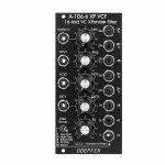
People also bought...
Doepfer A-106-6V 16-Fold VC XPander Filter Vintage Edition Module (black) (filter synth module)
Cat: 790473 Rel: 30 Oct 20 • View all Synth modules
Multimode filter module
Notes: Module A-106-6 is a multimode filter that is based on the filter circuit of the Oberheim Xpander. The module features 15 different filter types with 8 filters available simultaneously.
The toggle switch Filter Group is used to switch between 2 filter groups. These filter types are available:
1L (6 dB low pass)
2L (12 dB low pass)
3L (18 dB low pass)
4L (24 dB low pass)
1H (6 dB high pass)
2H (12 dB high pass)
3H (18 dB high pass)
2B (6 dB band pass)
4B (12 dB bandpass)
2N (notch)
3A (allpass)
2H1L (asymmetrical band pass made of a 12 dB high pass and a 6 dB low pass)
3H1L (asymmetrical band pass made of a 18 dB high pass and a 6 dB low pass)
2N1L (combination of notch and 6 dB low pass)
3A1L (combination of allpass and 6 dB low pass)
The module features voltage controlled resonance. For filter group 2 (2L, 4L, 2B ...) even self oscillation is possible. All standard VCF controls are available: manual filter frequency control Frq, one control voltage input with attenuator (FCV2)and one without attenuator (FCV1, ~ 1 V/octave). In addition voltage controlled resonance with manual control (Q) and a CV input with attenuator (QCV) are available. The circuit is based on a 24dB lowpass filter. The outputs of the four internal filter stages (i.e. the 6, 12, 18 and 24dB outputs) are mixed together with different levels and polarities to obtain 15 different filters. Because of this special circuit the outputs have slightly different levels and noise floor. This is caused by the different internal amplifications and numbers of stages that are required to generate the filter in question. If e.g. a filter is derived by one stage only (e.g. the 6 dB, 12dB, 18dB and 24dB low pass) the noise floor is smaller compared to a filter that is derived by a combination of all four filter stages. The module generates a distorted audio signal if the level control is set to about 50% (i.e. center position) or more with A-100 standard signals like VCOs.
Power consumption: 50mA at +12V and 50mA at -12V
Depth: 50mm
HP : 12
… Read moreThe toggle switch Filter Group is used to switch between 2 filter groups. These filter types are available:
1L (6 dB low pass)
2L (12 dB low pass)
3L (18 dB low pass)
4L (24 dB low pass)
1H (6 dB high pass)
2H (12 dB high pass)
3H (18 dB high pass)
2B (6 dB band pass)
4B (12 dB bandpass)
2N (notch)
3A (allpass)
2H1L (asymmetrical band pass made of a 12 dB high pass and a 6 dB low pass)
3H1L (asymmetrical band pass made of a 18 dB high pass and a 6 dB low pass)
2N1L (combination of notch and 6 dB low pass)
3A1L (combination of allpass and 6 dB low pass)
The module features voltage controlled resonance. For filter group 2 (2L, 4L, 2B ...) even self oscillation is possible. All standard VCF controls are available: manual filter frequency control Frq, one control voltage input with attenuator (FCV2)and one without attenuator (FCV1, ~ 1 V/octave). In addition voltage controlled resonance with manual control (Q) and a CV input with attenuator (QCV) are available. The circuit is based on a 24dB lowpass filter. The outputs of the four internal filter stages (i.e. the 6, 12, 18 and 24dB outputs) are mixed together with different levels and polarities to obtain 15 different filters. Because of this special circuit the outputs have slightly different levels and noise floor. This is caused by the different internal amplifications and numbers of stages that are required to generate the filter in question. If e.g. a filter is derived by one stage only (e.g. the 6 dB, 12dB, 18dB and 24dB low pass) the noise floor is smaller compared to a filter that is derived by a combination of all four filter stages. The module generates a distorted audio signal if the level control is set to about 50% (i.e. center position) or more with A-100 standard signals like VCOs.
Power consumption: 50mA at +12V and 50mA at -12V
Depth: 50mm
HP : 12
out of stock $167.97
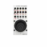
People also bought...
Doepfer A-174-4 3D Joystick Module (silver) (controller/CV modulation/expression module)
Cat: 765892 Rel: 30 Oct 20 • View all Synth modules
Control voltage module - 12HP
Notes: Module A-174-4 modules outputs three control voltages generated by a spring-loaded X/Y cross potentiometer (so-called joy stick) and a Gate signal. The control voltages for X and Y are controlled by the X and Y position of the joystick in the usual way. The third control voltage Z is controlled by the rotation of the spring-loaded joystick knob. The Gate signal is generated by a button at the center/top of the joystick knob.
For each control voltage the non-inverted signal (X, Y, Z) as well as the inverted signal with adjustable offset (-X+XO, -Y+YO, -Z+ZO) are available. The generic joystick control voltages are bipolar, i.e. they range from typ. -5V (lowest position) via 0V (center position) to typ. +5V (highest position). The "Overlap" switches can be used to add a fixed offset voltage of typ. +5V to the non-inverting output in question so that the output voltage range changes to typ. 0...+10V (rather than -5...+5V). That's necessary if e.g. a VCA has to be controlled, which requires a pure positive control voltage range. The switches are named "overlap" because they allow the overlapping of the non-inverting CV output (X, Y, Z) with the inverting output (-X+XO, -Y+YO, -Z+ZO) for crossfading applications. With the overlap switch "on" and appropriate setting of the offset control it's possible to obtain a control voltage range of 0...+10V for the non-inverting output and +10V...0V (i.e. same range but opposite direction) for the inverting output.
The offset voltages which are added to the inverting outputs can be adjusted by means of three small potentiometers. That way different kinds of control voltage ranges are possible, e.g.
-5V ... +5V for the non-inverting output and +5V ... -5V for the inverting output ( Overlap = off, Offset = 0)
0 ... +10V for the non-inverting output and +10V ... 0V for the inverting output ( Overlap = on, Offset = max)
-5V ... +5V for the non-inverting output and +10V ... 0V for the inverting output ( Overlap = off, Offset = max)
0 ... +10V for the non-inverting output and +5V ... -5V for the inverting output ( Overlap = on, Offset = 0)
On top of this the four quadrant voltages Q1, Q2, Q3 and Q4 are available. A quadrant voltage becomes positive when the joystick is positioned in the quadrant in question.
Each CV output is equipped with an LED that displays the present voltage.
Because of the construction height of the joystick (about 7 cm) the module cannot be installed into the cases A-100P6, A-100P9, A-100PMS6, A-100PMS9 and A-100PMS12 during transportation as the depth of the case cover is not sufficient. Into the base cases A-100PB and A-100PMB as well as in all other cases without cover the module can be installed without problems.
HP : 12
… Read moreFor each control voltage the non-inverted signal (X, Y, Z) as well as the inverted signal with adjustable offset (-X+XO, -Y+YO, -Z+ZO) are available. The generic joystick control voltages are bipolar, i.e. they range from typ. -5V (lowest position) via 0V (center position) to typ. +5V (highest position). The "Overlap" switches can be used to add a fixed offset voltage of typ. +5V to the non-inverting output in question so that the output voltage range changes to typ. 0...+10V (rather than -5...+5V). That's necessary if e.g. a VCA has to be controlled, which requires a pure positive control voltage range. The switches are named "overlap" because they allow the overlapping of the non-inverting CV output (X, Y, Z) with the inverting output (-X+XO, -Y+YO, -Z+ZO) for crossfading applications. With the overlap switch "on" and appropriate setting of the offset control it's possible to obtain a control voltage range of 0...+10V for the non-inverting output and +10V...0V (i.e. same range but opposite direction) for the inverting output.
The offset voltages which are added to the inverting outputs can be adjusted by means of three small potentiometers. That way different kinds of control voltage ranges are possible, e.g.
-5V ... +5V for the non-inverting output and +5V ... -5V for the inverting output ( Overlap = off, Offset = 0)
0 ... +10V for the non-inverting output and +10V ... 0V for the inverting output ( Overlap = on, Offset = max)
-5V ... +5V for the non-inverting output and +10V ... 0V for the inverting output ( Overlap = off, Offset = max)
0 ... +10V for the non-inverting output and +5V ... -5V for the inverting output ( Overlap = on, Offset = 0)
On top of this the four quadrant voltages Q1, Q2, Q3 and Q4 are available. A quadrant voltage becomes positive when the joystick is positioned in the quadrant in question.
Each CV output is equipped with an LED that displays the present voltage.
Because of the construction height of the joystick (about 7 cm) the module cannot be installed into the cases A-100P6, A-100P9, A-100PMS6, A-100PMS9 and A-100PMS12 during transportation as the depth of the case cover is not sufficient. Into the base cases A-100PB and A-100PMB as well as in all other cases without cover the module can be installed without problems.
HP : 12
1 in stock $148.00
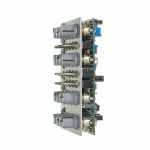
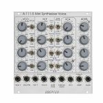
People also bought...
Doepfer A-111-5 Mini Synthesiser Voice Module (silver) (envelope generator/filter/LFO/oscillator/VCA/synth voice synth module)
Cat: 785445 Rel: 10 Sep 20 • View all Synth modules
A complete monophonic synthesiser module (modular version of Dark Energy).
Notes: A fully modular, Eurorack-format version of the excellent Dark Energy synth, the A-111-5 offers VCO, VCF, LFOs, VCA and envelope generator in a compact format. Brilliant value for a starter system.
Supplier's Notes:
Module A-111-5 is a complete monophonic synthesizer module that includes these components (modular version of Dark Energy):
VCO
Manual tune control (with an internal jumper the range can be set to ~ +/-1 half an octave or ~ +/-2.5 octaves)
Range switch -1 / 0 / +1 octave
Frequency range about 10Hz ... 12kHz - FM (frequency modulation) control with modulation source switch (LFO1 / off / ADSR)
Manual pulsewidth control for rectangle waveform
PWM control with modulation source switch (LFO2 / off / ADSR)
Waveform switch (sawtooth / off / triangle)
The sum of the waveform chosen by this switch and the rectangle is fed into the VCF (to turn the rectangle off the PW control has to be set fully CCW)
External CV input for VCO frequency (1V/octave)
External CV input for external PWM of the rectangle - internal CV input for frequency (1V/octave) connected to the A-100 bus via jumper, the jumper can be used to interrupt this internal connection if not wanted
VCF
24 dB low pass
~ 12 octaves frequency range
Manual frequency control
Tracking switch half - off - full (internally connected to the external frequency CV input of the VCO, i.e. the VCF tracks to the VCO if the switch is set to "half" or "full" position)
XM: exponential FM (frequency modulation) control with modulation source switch (LFO2 / off / ADSR)
LM: linear FM (frequency modulation) control to modulate the VCF by the triangle of the VCO in a linear (!) manner
Manual resonance control (up to self oscillation)
External audio input (this signal is added to the VCO signal)
External CV input for filter frequency - 1V/octave tracking for usage of the VCF as a sine wave oscillator (not as precise as the VCO but much better than most of the other filters)
VCA
Manual amplitude control
AM (amplitude modulation) control with modulation source switch (LFO1 / off / ADSR)
External CV input for VCA amplitude - special control scale: exponential scale in the range from about -20dB to -80/90dB, linear scale from about -20dB to 0dB (Remark: this special control scale results in a loudness behaviour that is a bit different from pure linear or exponential VCA)
LFO1 and LFO2
Manual frequency control
Waveform switch (triangle / off / rectangle)
Range switch (low, audio, medium) - LED display (dual green/red color for positive/negative share of the signal)
The inverted LFO1 signal is available as an additional socket (to use the LFO1 signal for external modules)
An internal jumper can be used to select between the LFO1 signal or the inverted LFO1 signal
ADSR
Manual controls for Attack, Decay, Sustain, Release
Range switch (long, short, medium) - blue LED display
ADSR signal is available as an additional socket (to use the ADSR signal for external modules)
Gate input connected to the A-100 bus via jumper, the jumper can be used to interrupt this internal connection if not wanted
Remarks:
As the LFO frequencies can go up to moderate audio range (~ 5kHz) even audio FM effects of VCO (pitch and pulsewidth), VCF and ADSR are possible.
If the VCO is turned off (waveform switch = center position, pulsewidth control = fully CCW) and the VCF resonance is set to maximum the module can be used as a sine oscillator. The sine can be modulated in a linear manner from the triangle wave of the VCO and by LFO2 in an exponential manner at the same time !
From the factory the socket labelled "LFO1" outputs the inverted LFO1 signal. But as the module has several internal pin headers available even another signal may appear at this socket by changing the internal module patch. These six pin headers are available: LFO1 output, LFO2 output, ADSR output, inverter input, inverter output, output socket. The internal default patch is LFO1 -> inverter input, inverter output -> output socket (i.e. socket = inverted LFO1). But even another signal can be patched to this socket (e.g. inverted ADSR, non-inverted LFO1, inverted or non-inverted LFO2). It is also possible to add a blind panel next to the A-111-5 with a couple of sockets that are connected to the corresponding pins of the A-111-5 pc board. The in- and outputs of the VCO, VCF and VCA are not available as pin headers because the VCO, VCF and VCA are internally connected in the circuit which is used in this module.
… Read moreSupplier's Notes:
Module A-111-5 is a complete monophonic synthesizer module that includes these components (modular version of Dark Energy):
VCO
Manual tune control (with an internal jumper the range can be set to ~ +/-1 half an octave or ~ +/-2.5 octaves)
Range switch -1 / 0 / +1 octave
Frequency range about 10Hz ... 12kHz - FM (frequency modulation) control with modulation source switch (LFO1 / off / ADSR)
Manual pulsewidth control for rectangle waveform
PWM control with modulation source switch (LFO2 / off / ADSR)
Waveform switch (sawtooth / off / triangle)
The sum of the waveform chosen by this switch and the rectangle is fed into the VCF (to turn the rectangle off the PW control has to be set fully CCW)
External CV input for VCO frequency (1V/octave)
External CV input for external PWM of the rectangle - internal CV input for frequency (1V/octave) connected to the A-100 bus via jumper, the jumper can be used to interrupt this internal connection if not wanted
VCF
24 dB low pass
~ 12 octaves frequency range
Manual frequency control
Tracking switch half - off - full (internally connected to the external frequency CV input of the VCO, i.e. the VCF tracks to the VCO if the switch is set to "half" or "full" position)
XM: exponential FM (frequency modulation) control with modulation source switch (LFO2 / off / ADSR)
LM: linear FM (frequency modulation) control to modulate the VCF by the triangle of the VCO in a linear (!) manner
Manual resonance control (up to self oscillation)
External audio input (this signal is added to the VCO signal)
External CV input for filter frequency - 1V/octave tracking for usage of the VCF as a sine wave oscillator (not as precise as the VCO but much better than most of the other filters)
VCA
Manual amplitude control
AM (amplitude modulation) control with modulation source switch (LFO1 / off / ADSR)
External CV input for VCA amplitude - special control scale: exponential scale in the range from about -20dB to -80/90dB, linear scale from about -20dB to 0dB (Remark: this special control scale results in a loudness behaviour that is a bit different from pure linear or exponential VCA)
LFO1 and LFO2
Manual frequency control
Waveform switch (triangle / off / rectangle)
Range switch (low, audio, medium) - LED display (dual green/red color for positive/negative share of the signal)
The inverted LFO1 signal is available as an additional socket (to use the LFO1 signal for external modules)
An internal jumper can be used to select between the LFO1 signal or the inverted LFO1 signal
ADSR
Manual controls for Attack, Decay, Sustain, Release
Range switch (long, short, medium) - blue LED display
ADSR signal is available as an additional socket (to use the ADSR signal for external modules)
Gate input connected to the A-100 bus via jumper, the jumper can be used to interrupt this internal connection if not wanted
Remarks:
As the LFO frequencies can go up to moderate audio range (~ 5kHz) even audio FM effects of VCO (pitch and pulsewidth), VCF and ADSR are possible.
If the VCO is turned off (waveform switch = center position, pulsewidth control = fully CCW) and the VCF resonance is set to maximum the module can be used as a sine oscillator. The sine can be modulated in a linear manner from the triangle wave of the VCO and by LFO2 in an exponential manner at the same time !
From the factory the socket labelled "LFO1" outputs the inverted LFO1 signal. But as the module has several internal pin headers available even another signal may appear at this socket by changing the internal module patch. These six pin headers are available: LFO1 output, LFO2 output, ADSR output, inverter input, inverter output, output socket. The internal default patch is LFO1 -> inverter input, inverter output -> output socket (i.e. socket = inverted LFO1). But even another signal can be patched to this socket (e.g. inverted ADSR, non-inverted LFO1, inverted or non-inverted LFO2). It is also possible to add a blind panel next to the A-111-5 with a couple of sockets that are connected to the corresponding pins of the A-111-5 pc board. The in- and outputs of the VCO, VCF and VCA are not available as pin headers because the VCO, VCF and VCA are internally connected in the circuit which is used in this module.
1 in stock $277.89
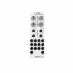
People also bought...
Doepfer A-135-3 Voltage Controlled Stereo Mixer Module (silver) (mixer/dual/stereo/quad/VCA synth module)
Cat: 781306 Rel: 28 Jul 20 • View all Synth modules
Stereo mixer module
Notes: Mix four stereo signals with CV control over levels. Doepfer's usual great value and user-friendly approach make this a great choice at an excellent price point.
Supplier notes:
A-135-3 is a is a voltage controlled stereo mixer with four inputs. Behind a front panel with 8 HP only eight linear VCAs (voltage controlled amplifiers) and the mixer based on the VCAs are available.
Controls, Inputs and Functions of each input:
Level (manual control of the VCA amplification), small rubberized knob (L1...L4)
Control voltage input with associated attenuator (CV 1...4), for the full VCA control range about 0...+5V control voltage are required (attenuator fully clockwise), for higher control voltages the attenuator is used, the attenuators are without knobs, just plastic shafts with white marker
Signal Input left/right (InL 1...4 / InR 1...4)
The signal inputs are not equipped with an attenuator. But the VCAs can process all signals up to 15Vpp / -7.5...+7.5V without clipping. In case of higher levels an external attenuator is required (e.g. A-183-1).
The sum of the left and right signals appear at the sockets Out L and Out R. The maximal amplification is about 0.5 to avoid clipping at the mixer outputs (otherwise the outputs may distort with 15Vpp signals at each signal input and full amplifications). If another maximal amplification (e.g. 1) is required two resistors have to be replaced.
All inputs and outputs are DC coupled. Consequently the module can be used to process both audio and control voltages.
Additional technical specification for each VCA (based on the specifications of the VCA circuits CEM3360/AS3360 used in the module):
Crosstalk between two channels: better than - 80dB
Signal attenuation at 0V CV: better than -80dB
Total harmonic distortion: typ. 1%
Control voltage feedthrough: max. 15mV
HP : 8
… Read moreSupplier notes:
A-135-3 is a is a voltage controlled stereo mixer with four inputs. Behind a front panel with 8 HP only eight linear VCAs (voltage controlled amplifiers) and the mixer based on the VCAs are available.
Controls, Inputs and Functions of each input:
Level (manual control of the VCA amplification), small rubberized knob (L1...L4)
Control voltage input with associated attenuator (CV 1...4), for the full VCA control range about 0...+5V control voltage are required (attenuator fully clockwise), for higher control voltages the attenuator is used, the attenuators are without knobs, just plastic shafts with white marker
Signal Input left/right (InL 1...4 / InR 1...4)
The signal inputs are not equipped with an attenuator. But the VCAs can process all signals up to 15Vpp / -7.5...+7.5V without clipping. In case of higher levels an external attenuator is required (e.g. A-183-1).
The sum of the left and right signals appear at the sockets Out L and Out R. The maximal amplification is about 0.5 to avoid clipping at the mixer outputs (otherwise the outputs may distort with 15Vpp signals at each signal input and full amplifications). If another maximal amplification (e.g. 1) is required two resistors have to be replaced.
All inputs and outputs are DC coupled. Consequently the module can be used to process both audio and control voltages.
Additional technical specification for each VCA (based on the specifications of the VCA circuits CEM3360/AS3360 used in the module):
Crosstalk between two channels: better than - 80dB
Signal attenuation at 0V CV: better than -80dB
Total harmonic distortion: typ. 1%
Control voltage feedthrough: max. 15mV
HP : 8
out of stock $128.57

People also bought...
Doepfer A-183-4 Quad Level Shifter Slim Line Series Module (utility/quad/digital/comparator synth module)
Cat: 765895 Rel: 28 Jul 20 • View all Synth modules
Quad level shifter module - 2HP.
Notes: Module A-183-4 is a fourfold level shifter. A level shifter is required if the level of a digital control signal has to be increased or decreased. A typical application is the conversion of a gate, trigger or clock signal with +5V voltage level (tolerance range +2...+5V) to +12 voltage level. The output voltage level can be set by means of a jumper to +12V or +5V. The factory setting is +12V. But it can be changed to convert also a higher to a lower level (e.g. +12V to +5V). But this application is required rarely. The output level setting by means of the jumper is global, i.e. it is valid for all four units and cannot be set individually for each unit. The four output signals are displayed by means of LEDs.
The outputs and inputs of the four sub-units are normalled via the switching contacts of the input sockets, i.e. the output signal of the upper unit is used as input signal of the unit below provided that no patch cable is inserted into the input socket of the lower unit. That way the module can be used also as clock/trigger/gate buffer or buffered multiple for digital signals. For this the signal that has to be buffered is connected to input 1. The buffered (and possible level shifted) signal appears then at all four outputs.
Voltage thresholds for the input voltages:
voltages below +0,8 V are treated as "low"
voltages above +3 V are treated as "high"
Typical applications:
Converting the levels of digital control signals (e.g. gate, trigger, clock) to another voltage level (+12V or +5V)
buffering and duplicating digital control signals (e.g. gate, trigger, clock)
Important note: the module cannot be used for analog signals.
… Read moreThe outputs and inputs of the four sub-units are normalled via the switching contacts of the input sockets, i.e. the output signal of the upper unit is used as input signal of the unit below provided that no patch cable is inserted into the input socket of the lower unit. That way the module can be used also as clock/trigger/gate buffer or buffered multiple for digital signals. For this the signal that has to be buffered is connected to input 1. The buffered (and possible level shifted) signal appears then at all four outputs.
Voltage thresholds for the input voltages:
voltages below +0,8 V are treated as "low"
voltages above +3 V are treated as "high"
Typical applications:
Converting the levels of digital control signals (e.g. gate, trigger, clock) to another voltage level (+12V or +5V)
buffering and duplicating digital control signals (e.g. gate, trigger, clock)
Important note: the module cannot be used for analog signals.
out of stock $54.95
People also bought...
Doepfer A-130-8 Octal Linear VCA/Voltage Controlled Mixers Slim Line Series Module (silver) (mixer/Quad/VCA synth module)
Cat: 765896 Rel: 28 Jul 20 • View all Synth modules
linear VCA module
Notes: Lots of functionality in a compact format thanks to Doepfer's typically smart approach. Eight linear VCAs with three mixers built in for good measure. Can be used for both audio and CV signals. Versatile.
Supplier notes:
Module A-130-8 contains eight linear voltage controlled amplifiers (VCAs). Each VCA features a control voltage input (CV), a signal input (In) and a signal output (Out). In addition three mixers are included: the socket labelled "1-4" outputs the sum of the VCAs 1-4, the socket labelled "5-8" outputs the sum of the VCAs 5-8, the socket labelled "1-8" outputs the sum of all eight VCAs.
The signal inputs are able to process levels up to 10Vpp without clipping. Each CV input is equipped with a trimming potentiometer that is used to adjust the sensitivity of the CV input in question. In the factory the module is adjusted for the CV range 1...+5V but can be re-adjusted by the user for other control voltage ranges (e.g. 0...+10V).
The amplification range for each single VCA is 0...1. The signals of the sum outputs have a lower amplification to avoid distortion.
The VCAs and mixers are fully DC coupled, i.e. the module can be used for the processing of both audio and control voltage signals. The control voltage and signal inputs can be normalled by means of small solder pads (e.g. 1 > 2 > 3 > 4 and so on, or 1 > 5, 2 > 6, 3 > 7, 4 > 8 for the stereo application mentioned below).
Typical applications:
any kind of VCA application (e.g. voltage controlled attenuation of audio or control voltage signals)
two voltage controlled mixers with four channels each
voltage controlled stereo mixer with four channels each, for this the control voltage inputs have to be correspondingly patched or internally normalled: CV1=CV5 /CV 2=CV6 / CV3=CV7 / CV4=CV8
voltage controlled mixer with eight channels
add-on for the planned Joystick module A-174-4
HP : 6
… Read moreSupplier notes:
Module A-130-8 contains eight linear voltage controlled amplifiers (VCAs). Each VCA features a control voltage input (CV), a signal input (In) and a signal output (Out). In addition three mixers are included: the socket labelled "1-4" outputs the sum of the VCAs 1-4, the socket labelled "5-8" outputs the sum of the VCAs 5-8, the socket labelled "1-8" outputs the sum of all eight VCAs.
The signal inputs are able to process levels up to 10Vpp without clipping. Each CV input is equipped with a trimming potentiometer that is used to adjust the sensitivity of the CV input in question. In the factory the module is adjusted for the CV range 1...+5V but can be re-adjusted by the user for other control voltage ranges (e.g. 0...+10V).
The amplification range for each single VCA is 0...1. The signals of the sum outputs have a lower amplification to avoid distortion.
The VCAs and mixers are fully DC coupled, i.e. the module can be used for the processing of both audio and control voltage signals. The control voltage and signal inputs can be normalled by means of small solder pads (e.g. 1 > 2 > 3 > 4 and so on, or 1 > 5, 2 > 6, 3 > 7, 4 > 8 for the stereo application mentioned below).
Typical applications:
any kind of VCA application (e.g. voltage controlled attenuation of audio or control voltage signals)
two voltage controlled mixers with four channels each
voltage controlled stereo mixer with four channels each, for this the control voltage inputs have to be correspondingly patched or internally normalled: CV1=CV5 /CV 2=CV6 / CV3=CV7 / CV4=CV8
voltage controlled mixer with eight channels
add-on for the planned Joystick module A-174-4
HP : 6
1 in stock $97.98
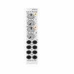
People also bought...
Doepfer A-133-2 Dual Voltage Controlled VCA/Polarizer/Inverter/Ring Modulator Module (silver) (attenuator/dual/stereo/polarizer/ring modulator/VCA synth module)
Cat: 765897 Rel: 28 Jul 20 • View all Synth modules
VCA/polarizer/inverter/ring modulator module
Notes: A-133-2 is the slim version of the A-133 but has some additional features and improvements available compared to the A-133.
Module A-133-2 can be used for a lot of applications: as a simple VCA, or a voltage controlled polarizer/attuverter, or a voltage controlled inverter up to a DC coupled ring modulator. In principle the module contains two special voltage controlled amplifiers (VCAs) that allow both positive and negative amplification.
The overall amplification is definded by the sum of the voltage generated by the Man control, the external control voltage CV and the position of the CV control which works as an attenuator for the external control voltage. Without external CV the amplification is +1 when the Man control is fully CW. In the center position the amplification is zero and fully CCW it's -1 (i.e. the incoming signal is inverted). By means of the external control voltage CV the manually adjusted amplification can be modulated. CV can be both positive or negative (i.e. bipolar) to obtain positive or negative amplification values controlled by the external CV.
In addition the CV signal can be modulated via the modulation control input Mod by means of another control voltage. The Mod socket is normalled to +5V, i.e. a constant positive voltage is used as modulation CV provided that no plug is inserted into the Mod socket.
The current amplification is displayed by a dual color LED (note: it's not a signal display but indicates the amplification, probably yellow = positive amplification, red = negative amplification)
Application examples:
voltage controlled amplifier (VCA) with pure positive overall amplification (Man + CV)
voltage controlled inverter with pure negative overall amplification (Man + CV)
voltage controlled polarizer/attuverter overall amplification changing between positive and negative (Man + CV)
DC coupled ring modulator with offset feature, the "classical" ring modulator corresponds to Man=0 and symmetrical audio signals for In and CV
additional effects by means of the modulation feature of the CV signal (using the Mod input)
… Read moreModule A-133-2 can be used for a lot of applications: as a simple VCA, or a voltage controlled polarizer/attuverter, or a voltage controlled inverter up to a DC coupled ring modulator. In principle the module contains two special voltage controlled amplifiers (VCAs) that allow both positive and negative amplification.
The overall amplification is definded by the sum of the voltage generated by the Man control, the external control voltage CV and the position of the CV control which works as an attenuator for the external control voltage. Without external CV the amplification is +1 when the Man control is fully CW. In the center position the amplification is zero and fully CCW it's -1 (i.e. the incoming signal is inverted). By means of the external control voltage CV the manually adjusted amplification can be modulated. CV can be both positive or negative (i.e. bipolar) to obtain positive or negative amplification values controlled by the external CV.
In addition the CV signal can be modulated via the modulation control input Mod by means of another control voltage. The Mod socket is normalled to +5V, i.e. a constant positive voltage is used as modulation CV provided that no plug is inserted into the Mod socket.
The current amplification is displayed by a dual color LED (note: it's not a signal display but indicates the amplification, probably yellow = positive amplification, red = negative amplification)
Application examples:
voltage controlled amplifier (VCA) with pure positive overall amplification (Man + CV)
voltage controlled inverter with pure negative overall amplification (Man + CV)
voltage controlled polarizer/attuverter overall amplification changing between positive and negative (Man + CV)
DC coupled ring modulator with offset feature, the "classical" ring modulator corresponds to Man=0 and symmetrical audio signals for In and CV
additional effects by means of the modulation feature of the CV signal (using the Mod input)
1 in stock $97.47
People also bought...
Cat: 769128 Rel: 17 Jul 20 • View all Audiokabel
Modular patch cable
Notes: Patch cable for modular synthesizer 80 cm, transparent, mono jack plug 3.5 mm at each end.
… Read moreMore than 10 in stock $2.59
