100% Sicheres Einkaufen
Studio equipment
Our full range of studio equipment from all the leading equipment and software brands. Guaranteed fast delivery and low prices.
100% Sicheres Einkaufen
DJ equipment
Our full range of DJ equipment from all the leading equipment and software brands. Guaranteed fast delivery and low prices. Visit Juno DJ

Hilfe
BestellenProbleme beim BestellenHäufig gestellte FragenKontaktiere unsKontaktiere uns (Lieferanten)Über JunoJuno DailyNeuerscheinungen dieser WocheDJ & Studio StoreTagsFeedbackDatenschutzregelungReturns & refundsAGBFinanceJuno Vinyl DistributionJuno Vinyl WholesaleJuno Marketing and PR departmentPromote your label / releases


Filter
Stock

Coming Soon
Equipment
Format
Brand
Featured
Price
Tags
People also bought...
Doepfer A-138c Polarizing Mixer Module (synth module)
Cat: 716943 Rel: 29 Jan 19 • View all Synth modules
Four channel mixer for mixing control signals - 8HP
Notes: Module A-138c is a four channel mixer, that allows to add or to subtract four incoming voltages to the output signal. In the middle position of the corresponding control the amplification is zero. Turning the knob counter-clockwise the signal is subtracted from the output sum with increasing amount. Turning the knob clockwise the signal is added to the output sum with increasing amount. The output control works in the same way, i.e. the resulting output signal can be additionally attenuated and/or inverted.
The module is used in the first place to mix control voltages (e.g. ADSR, LFO). It can be used to mix audio signals too but there is no difference between adding and subtracting audio signals unless they have a fixed phase relationship (e.g. the outputs of a VCO, or the input and output signal of a VCF). For audio signals without phase correlation there is no difference between addition and subtraction.
Control In1 works as a DC offset generator (about -5V...+5V) provided that no patch cord is plugged into socket In1. If this feature is not required it can be deactivated by removing a jumper on the pc board.
The voltage controlled version of a polarizer is the module A-133.
… Read moreThe module is used in the first place to mix control voltages (e.g. ADSR, LFO). It can be used to mix audio signals too but there is no difference between adding and subtracting audio signals unless they have a fixed phase relationship (e.g. the outputs of a VCO, or the input and output signal of a VCF). For audio signals without phase correlation there is no difference between addition and subtraction.
Control In1 works as a DC offset generator (about -5V...+5V) provided that no patch cord is plugged into socket In1. If this feature is not required it can be deactivated by removing a jumper on the pc board.
The voltage controlled version of a polarizer is the module A-133.
out of stock $65.38
People also bought...
Doepfer A-138d Crossfader/FX Insert Module (external/mixer synth module)
Cat: 716947 Rel: 29 Jan 19 • View all Synth modules
Crossfader for two different A-100 signals, plus insert for external effects
Notes: The A-138d primarily is used for crossfading between two modular signals. On the other hand you can used it for inserting stompboxes or other effects into your modular system. Both the inputs and the mix output are available twice, like a mini-multiples e.g. for using the input signal also for other applications, kind of like a Thru.
Crossfader: With the crossfading control CF you blend manually between the inputs In 1 and In 2. The Mute switch allows for muting one of the two signals, independent on the crossfader position.
Effect insert: The signal at input In1 is emitted at the FX Send output and can be attenuated with the Atten. control because the modular system works with much higher levels.
The effect unit's output is inserted to the FX Return input socket and its level can be boosted with the Amp. control. The processed signal is available at the bottom in 2 socket.
Use the CF control to blend between the original signal and the effect signal and to mute switch for quick muting e.g. of the effect return signal.
… Read moreCrossfader: With the crossfading control CF you blend manually between the inputs In 1 and In 2. The Mute switch allows for muting one of the two signals, independent on the crossfader position.
Effect insert: The signal at input In1 is emitted at the FX Send output and can be attenuated with the Atten. control because the modular system works with much higher levels.
The effect unit's output is inserted to the FX Return input socket and its level can be boosted with the Amp. control. The processed signal is available at the bottom in 2 socket.
Use the CF control to blend between the original signal and the effect signal and to mute switch for quick muting e.g. of the effect return signal.
1 in stock $68.49
People also bought...
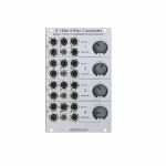
Doepfer A-138e Quad 3-Way Crossfader/Mixer/Polarizer Module (synth module)
Cat: 716951 Rel: 29 Jan 19 • View all Synth modules
19HP Eurorack module for attenuating, polarizing & crossfading audio or control signals
Notes: Module A-138e contains four identical units that can be used for different crossfading, mixing and polarizing applications:
Polarizer: only input A is used, inputs B and C are unconnected. In this case the sub-unit works as a polarizer. In the CCW position of the control the signal connected to input A appears at the output, in the CW position the inverted signal, in the centre position no signal appears at the output
Two-way Crossfader type 1: Two different signals are connected to the inputs A and C, switch is in the left position (switching contact of input B is open). In this case the sub-unit works as two-way crossfader between the two signals connected to the inputs A and C. In the centre position both signals appear with the same level.
Two-way attenuator: Two different signals are connected to the inputs A and C, switch is in the right position (switching contact of input B is connected to GND). In this case control is used to attenuate signal A (between CCW and centre position) or signal C (between centre and CW position). In the centre position no signal appears at the output. Similar to the two-way crossfader but without signal in the centre position.
Three-way Crossfader: Three different signals are connected to the inputs A, B and C. In this case the sub-unit works as three-way crossfader. In the CCW position only signal A appears at the output. Between CCW and centre position a mix of the signals A and B appears at the output. In the centre position only signal B appears at the output. Between centre and CW position a mix of signals B and C appears at the output. In the CW position only signal C appears at the output.
Two-way Crossfader/Polarizer type 2: Two different signals are connected to the inputs A and B. In the CCW position only signal A appears at the output. Between CCW and centre position a mix of the signals A and B appears at the output. In the centre position only signal B appears at the output. Between centre and CW position a mix of signals B and inverted signal A appears at the output. In the CW position only the inverted signal A appears at the output. Useful for CV mixing: e.g. signal A = ADSR, signal B = LFO. In this case one can fade between ADSR ... LFO + ADSR ... LFO ... LFO - ADSR ... - ADSR.
In addition, the inverted signal of input A is available as a separate output. Potentiometers with centre detent and centre terminal are used as controls.
… Read morePolarizer: only input A is used, inputs B and C are unconnected. In this case the sub-unit works as a polarizer. In the CCW position of the control the signal connected to input A appears at the output, in the CW position the inverted signal, in the centre position no signal appears at the output
Two-way Crossfader type 1: Two different signals are connected to the inputs A and C, switch is in the left position (switching contact of input B is open). In this case the sub-unit works as two-way crossfader between the two signals connected to the inputs A and C. In the centre position both signals appear with the same level.
Two-way attenuator: Two different signals are connected to the inputs A and C, switch is in the right position (switching contact of input B is connected to GND). In this case control is used to attenuate signal A (between CCW and centre position) or signal C (between centre and CW position). In the centre position no signal appears at the output. Similar to the two-way crossfader but without signal in the centre position.
Three-way Crossfader: Three different signals are connected to the inputs A, B and C. In this case the sub-unit works as three-way crossfader. In the CCW position only signal A appears at the output. Between CCW and centre position a mix of the signals A and B appears at the output. In the centre position only signal B appears at the output. Between centre and CW position a mix of signals B and C appears at the output. In the CW position only signal C appears at the output.
Two-way Crossfader/Polarizer type 2: Two different signals are connected to the inputs A and B. In the CCW position only signal A appears at the output. Between CCW and centre position a mix of the signals A and B appears at the output. In the centre position only signal B appears at the output. Between centre and CW position a mix of signals B and inverted signal A appears at the output. In the CW position only the inverted signal A appears at the output. Useful for CV mixing: e.g. signal A = ADSR, signal B = LFO. In this case one can fade between ADSR ... LFO + ADSR ... LFO ... LFO - ADSR ... - ADSR.
In addition, the inverted signal of input A is available as a separate output. Potentiometers with centre detent and centre terminal are used as controls.
out of stock $76.80
People also bought...
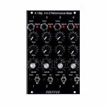
Doepfer A-138oV Performance Mixer Output Vintage Edition Module (black) (mixer/expander synth module)
Cat: 716953 Rel: 29 Jan 19 • View all Synth modules
Output module for combining with one or more A-138p
Notes: Modules A-138p/o are used to build a simple performance mixer (instead of an external stand-alone mixer). Module A-138p is the 4-fold input module, A-138o is the output module that can be combined with one or more A-138p, or A-135-A/B modules.
A-138o features:
- Level controls for Left, Right and Aux
- Output sockets for Left, Right and Aux (3.5 mm mono sockets)
- A-138o requires at least one A-138p (no stand-alone use)
- Application example for Aux Send and Aux Return: looping in another module for effects (e.g. DSP module A-187-1, BBD module A-188-1, Spring Reverb A-199)
- Application example for Aux Send only: pre-listening in combination with the headphone amplifier module A-139-2
- 3U Eurorack module, 4HP wide, 40mm deep
- Current draw: 20mA at +12V and 12V at -12V
… Read moreA-138o features:
- Level controls for Left, Right and Aux
- Output sockets for Left, Right and Aux (3.5 mm mono sockets)
- A-138o requires at least one A-138p (no stand-alone use)
- Application example for Aux Send and Aux Return: looping in another module for effects (e.g. DSP module A-187-1, BBD module A-188-1, Spring Reverb A-199)
- Application example for Aux Send only: pre-listening in combination with the headphone amplifier module A-139-2
- 3U Eurorack module, 4HP wide, 40mm deep
- Current draw: 20mA at +12V and 12V at -12V
out of stock $60.97
People also bought...
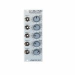
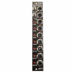
Doepfer A-138pv 4-In-2 Performance Mixer Vintage Edition Module (black) (mixer synth module)
Cat: 716956 Rel: 29 Jan 19 • View all Synth modules
4-way input module - 16HP
Notes: Modules A-138p/o are used to built a simple performance mixer (instead of an external stand-alone mixer). Module A-138p is the 4-fold input module, A-138o is the output module that can be combined with one or more A-138p.
A-138p features:
- 4 channels
- Controls and inputs for each channel
- Input (3.5 mm mono socket)
- Signal LED (as a coarse monitor of the incoming level, the level is measured after the gain control)
- Mute switch
- Gain (control to adapt different audio levels)
- Level (the main volume control)
- Aux
- Pan
- Internal jumper for each channel to choose between Aux pre/post main Level control
- Internal connection to the output module and to other A-138p modules
Doepfer A-138p requires A-138o (no stand-alone use).
… Read moreA-138p features:
- 4 channels
- Controls and inputs for each channel
- Input (3.5 mm mono socket)
- Signal LED (as a coarse monitor of the incoming level, the level is measured after the gain control)
- Mute switch
- Gain (control to adapt different audio levels)
- Level (the main volume control)
- Aux
- Pan
- Internal jumper for each channel to choose between Aux pre/post main Level control
- Internal connection to the output module and to other A-138p modules
Doepfer A-138p requires A-138o (no stand-alone use).
out of stock $139.60

People also bought...
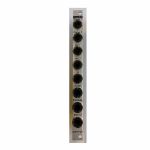
Doepfer A-138m 4x4 Matrix Mixer Module (attenuator/mixer/quad module)
Cat: 716959 Rel: 29 Jan 19 • View all Synth modules
4x4 matrix mixer module - 20HP
Notes: Module A-138m is a 4 x 4 matrix mixer with switches for unipolar/bipolar mode for each column. Unipolar means that the controls work as attenuators. Bipolar means that the controls work as polarizers. In this mode the amplification is zero in the middle position of the corresponding control. Turning the knob counterclockwise from the center position the signal is subtracted from the output sum with increasing amount (i.e. negative). Turning the knob clockwise from the center position the signal is added to the output sum with increasing amount. The module is DC-coupled and can be used for both audio and control voltage mixing.
By means of an internal jumper one can select if the four upper controls work as DC offset generators - provided that no patch cord is plugged into the upper input socket. If this feature is not required it can be deactivated by removing the jumper on top left of the pc board. The function is identical to the A-138a/b.
Dimensions
20 HP
20 mm deep
Current Draw
30 mA +12V
30 mA -12V
… Read moreBy means of an internal jumper one can select if the four upper controls work as DC offset generators - provided that no patch cord is plugged into the upper input socket. If this feature is not required it can be deactivated by removing the jumper on top left of the pc board. The function is identical to the A-138a/b.
Dimensions
20 HP
20 mm deep
Current Draw
30 mA +12V
30 mA -12V
out of stock $128.70

People also bought...
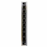
Doepfer A-138u 2x3 Dual Micro Mixer Module (synth module)
Cat: 716960 Rel: 29 Jan 19 • View all Synth modules
Eurorack mixer for audio signals or control voltages - 4HP
Notes: Module A-138u is a simple, low-cost mixer with two units. Each unit is equipped with three inputs and one output. The upper unit has for each input a trimming potentiometer available that works as attenuator and allows to adjust the amplification in the range 0...+1. In the lower unit only the third input is equipped with such an attenuator. The factory setting is amplification = 1 for all inputs.
The output of the upper unit is normalled to the first input of the lower unit. That way the module can be used also as a mixer with five inputs: for this the inputs 1, 2 and 3 of the upper unit and the inputs 2 and 3 of the lower unit are used. The sum output for all five signals is then the output of the lower unit. As soon as a plug is inserted into input 1 of the lower unit the module becomes a dual 3-in-1 mixer again.
Inputs and Outputs are DC-coupled, i.e. audio and control signals can be mixed.
Application examples:
Mixer for audio signals, e.g. three VCOs preceding a VCF, when the amplifications are adjusted slightly different no signal extinction occurs during the beat of the VCOs
Mixer for control voltages (e.g. LFOs, envelope generators, random voltages)
… Read moreThe output of the upper unit is normalled to the first input of the lower unit. That way the module can be used also as a mixer with five inputs: for this the inputs 1, 2 and 3 of the upper unit and the inputs 2 and 3 of the lower unit are used. The sum output for all five signals is then the output of the lower unit. As soon as a plug is inserted into input 1 of the lower unit the module becomes a dual 3-in-1 mixer again.
Inputs and Outputs are DC-coupled, i.e. audio and control signals can be mixed.
Application examples:
Mixer for audio signals, e.g. three VCOs preceding a VCF, when the amplifications are adjusted slightly different no signal extinction occurs during the beat of the VCOs
Mixer for control voltages (e.g. LFOs, envelope generators, random voltages)
out of stock $49.81
People also bought...
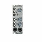
Doepfer A-160-2v Clock/Trigger Divider II Vintage Edition Module (black) (clock modulator/frequency divider synth module)
Cat: 864696 Rel: 14 Mar 22 • View all Synth modules
Module A-160-2 is an enhanced version of the standard clock divider A-160.
Notes: Module A-160-2V is an enhanced version of the standard clock divider A-160. The module is a frequency divider for clock/trigger/gate signals, designed to be a source of lower frequencies, particularly for rhythm uses.
The Clock input will take any digital signal from, eg., an LFO, MIDI sync, or the gate from a MIDI-CV interface. At the outputs, you have access to three sets of seven different sub-divided clock signals, from half the clock frequency down to 1/128. The low/high levels of the output signals are 0V and about +10V.
The A-160-2V also has a reset input. Whenever a reset signal is sensed, all outputs are set to certain levels which depend upon the selected mode.
HP : 4
… Read moreThe Clock input will take any digital signal from, eg., an LFO, MIDI sync, or the gate from a MIDI-CV interface. At the outputs, you have access to three sets of seven different sub-divided clock signals, from half the clock frequency down to 1/128. The low/high levels of the output signals are 0V and about +10V.
The A-160-2V also has a reset input. Whenever a reset signal is sensed, all outputs are set to certain levels which depend upon the selected mode.
HP : 4
5 in stock $107.94
Click for better price!
or call +44 20 7424 1960
quote 864696
quote 864696
People also bought...
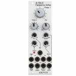
Doepfer A-126-2exp Voltage Controlled Frequency Shifter II - Expansion Module (silver) (expander synth module)
Cat: 852803 Rel: 04 Feb 22 • View all Synth modules
An expander for the A-126-2 Voltage Controlled Frequency Shifter.
Notes: The Doepfer A-126-2exp is an expander for the A-126-2 Voltage Controlled Frequency Shifter.
It adds two outputs from the Dome filter (+45 and -45 degrees) as well as separate outputs from the ring modulators 1 and 2, and from the internal envelope generator. Furthermore, it offers dedicated outputs for Up and Down Shift, allowing the module to be patched in stereo.
*Note: The expander can only be used in conjunction with the module A-126-2.
HP : 2
… Read moreIt adds two outputs from the Dome filter (+45 and -45 degrees) as well as separate outputs from the ring modulators 1 and 2, and from the internal envelope generator. Furthermore, it offers dedicated outputs for Up and Down Shift, allowing the module to be patched in stereo.
*Note: The expander can only be used in conjunction with the module A-126-2.
HP : 2
1 in stock $52.41
Click for better price!
or call +44 20 7424 1960
quote 852803
quote 852803
People also bought...
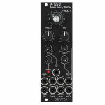
Doepfer A-126-2exp Voltage Controlled Frequency Shifter II - Expansion Vintage Edition Module (black) (expander synth module)
Cat: 852807 Rel: 04 Feb 22 • View all Synth modules
An expander for the A-126-2 Voltage Controlled Frequency Shifter.
Notes: The Doepfer A-126-2exp is an expander for the A-126-2 Voltage Controlled Frequency Shifter.
It adds two outputs from the Dome filter (+45 and -45 degrees) as well as separate outputs from the ring modulators 1 and 2, and from the internal envelope generator. Furthermore, it offers dedicated outputs for Up and Down Shift, allowing the module to be patched in stereo.
*Note: The expander can only be used in conjunction with the module A-126-2.
HP : 2
… Read moreIt adds two outputs from the Dome filter (+45 and -45 degrees) as well as separate outputs from the ring modulators 1 and 2, and from the internal envelope generator. Furthermore, it offers dedicated outputs for Up and Down Shift, allowing the module to be patched in stereo.
*Note: The expander can only be used in conjunction with the module A-126-2.
HP : 2
2 in stock $51.89
Click for better price!
or call +44 20 7424 1960
quote 852807
quote 852807

People also bought...
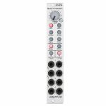
Doepfer A-124 Wasp Filter SE Module (special edition black & yellow version) (B-STOCK) (synth module)
Cat: 820032 Rel: 29 Nov 17 • View all Synth modules
B-STOCK: Item refurbished, repaired and in perfect working order.
Notes: ***B-STOCK: Item refurbished, repaired and in perfect working order.***
Module A-124 is a special 12dB multimode filter using the "strange" filter circuit of the "EDP Wasp" (an analog synthesizer with black/yellow case built end of the seventies, manufactured by the UK company "Electronic Dream Plant" with Chris Huggett und Adrian Wagner). This design "abuses" digital inverters as analog operational amplifiers leading to distortions and other "dirty" effects that generate the specific sound of this filter. The filter is equipped with a band pass output and a combined low/notch/high pass output. For this output a control knob defines the relation between low and high pass signal. If both signals appear at the same level (i.e. middle position of the Mix knob) one obtains a notch filter. Otherwise the low or high pass signal predominates. The module does not feature self-oscillation in contrast to most of the other filters of the A-100 system.
Inputs: Audio In, CV In (2x)
Outputs: Bandpass Out, Low/Highpass Mix-Out
Controls: Audio and CV attenuator, Frequency, Resonance, LP/HP Mix
The function and operation of this module is very similar to the module SEM VCF A-106-5. But the sound of both filters is very different! The only functional difference is the position of the sockets and controls, and the function of the controls CV2 (A-124: normal attenuator, A-106-5: polarizer).
- 3U Eurorack module, 8HP wide, 45mm deep
- Current draw 30mA
… Read moreModule A-124 is a special 12dB multimode filter using the "strange" filter circuit of the "EDP Wasp" (an analog synthesizer with black/yellow case built end of the seventies, manufactured by the UK company "Electronic Dream Plant" with Chris Huggett und Adrian Wagner). This design "abuses" digital inverters as analog operational amplifiers leading to distortions and other "dirty" effects that generate the specific sound of this filter. The filter is equipped with a band pass output and a combined low/notch/high pass output. For this output a control knob defines the relation between low and high pass signal. If both signals appear at the same level (i.e. middle position of the Mix knob) one obtains a notch filter. Otherwise the low or high pass signal predominates. The module does not feature self-oscillation in contrast to most of the other filters of the A-100 system.
Inputs: Audio In, CV In (2x)
Outputs: Bandpass Out, Low/Highpass Mix-Out
Controls: Audio and CV attenuator, Frequency, Resonance, LP/HP Mix
The function and operation of this module is very similar to the module SEM VCF A-106-5. But the sound of both filters is very different! The only functional difference is the position of the sockets and controls, and the function of the controls CV2 (A-124: normal attenuator, A-106-5: polarizer).
- 3U Eurorack module, 8HP wide, 45mm deep
- Current draw 30mA
out of stock $72.43
People also bought...
Doepfer A-126-2 Frequency Shifter Eurorack Module (eurorack oscillator/phase shifter/pitch shifter/VCA module)
Cat: 847081 Rel: 17 Nov 21 • View all Synth modules
Voltage Controlled Frequency Shifter II
Notes: Module A-126-2 is a fully analog frequency shifter for audio signals. A frequency shifter is an audio processing unit that shifts each frequency of the incoming audio signal by the same frequency. If the shifting frequency is e.g. 200Hz an incoming audio frequency of 1000 Hz becomes 1200 Hz, 2000Hz becomes 2200 Hz, 3000 Hz becomes 3200 Hz and so on. Pay attention that this is different from pitch shifting where all frequencies are shifted proportional (e.g. 1000>1200Hz, 2000>2400Hz, 3000>3600Hz) !
The frequency range of the internal quadrature VCO is about 8 octaves (about 20Hz ... 5kHz). If required an external quadrature VCO can be used.
The module is equipped with these controls, inputs and outputs:
Frequ. 1: first manual control of the shifting frequency (factory setting: coarse, range about 20Hz - 5 kHz)
Frequ. 2: second manual control of the shifting frequency (factory setting: fine)
by means of internal jumpers the sensitivity of Frequ.1 and 2 can be swapped (i.e. Frequ.1 = fine and Frequ.2 = coarse)
the relation between coarse and fine control is about 25:1 (corresponding to about 8 octaves to 1/3 octave)
FCV In (socket) and FCV (small control without knob): control voltage input with attenuator for the external voltage control of the shifting frequency
Mix: manual control of the up/down shift panning unit, fully CCW = down shift, fully CW = up shift, in between a mixture of down and up
Mix CV In (socket) and Mix CV (small control without knob): control voltage input with attenuator for the mixing unit for external voltage control of the up/down mixing
Audio In (socket), Level (small control without knob) and Overload (LED): audio input with attenuator, typ. audio in level = 1Vpp, the level control has to be adjusted so that the overload LED just begins to light up a bit, when the LED is fully on clipping/distortion occurs, when the LED is permanently off the input level is too low and the signal-to-noise ratio increases
Audio Out (socket): audio output of the frequency shifter
Squelch (small control without knob): controls the squelch function: fully CCW (Env.) the output VCA is controlled by the envelope signal, which is derived from the audio input signal, fully CW (open) the output VCA is permanently open (no squelch function), in between the squelch intensity can be adjusted
Quadrature VCO Outputs (sockets Sin and Cos): outputs of the internal quadrature oscillator, about 12Vpp level (+6V/-6V)
Ext. Inputs Sin and Cos (sockets): required when an external quadrature VCO (e.g. A-143-9 with a wider frequency range or A-110-4 with thru zero feature or A-110-6 with different waveforms) is used instead of the internal quadrature VCO, the levels of the external VCO should be about 10Vpp (8...10Vpp are OK) and the signals have to be symmetrical around zero Volts, the sockets are normalled to the internal quadrature VCO (i.e. the sockets are equipped with switching contacts that interrupt the internal connection as soon as a plug inserted)
VCA ext. CV (socket): used when an external control voltage (e.g. from an envelope generator) should be used to control the output VCA instead of the internal squelch unit, the socket is normalled to the output of the squelch control (i.e. the socket is equipped with a switching contact that interrupts the internal squelch connection as soon as a plug inserted). From about +8V external control voltage the VCA is fully open.
Internal terminals (pin headers, e.g. for a DIY breakout module):
envelope follower output
dome filter output 1
dome filter output 2
ring modulator 1 output
ring modulator 2 output
Up shift output
Down shift output
… Read moreThe frequency range of the internal quadrature VCO is about 8 octaves (about 20Hz ... 5kHz). If required an external quadrature VCO can be used.
The module is equipped with these controls, inputs and outputs:
Frequ. 1: first manual control of the shifting frequency (factory setting: coarse, range about 20Hz - 5 kHz)
Frequ. 2: second manual control of the shifting frequency (factory setting: fine)
by means of internal jumpers the sensitivity of Frequ.1 and 2 can be swapped (i.e. Frequ.1 = fine and Frequ.2 = coarse)
the relation between coarse and fine control is about 25:1 (corresponding to about 8 octaves to 1/3 octave)
FCV In (socket) and FCV (small control without knob): control voltage input with attenuator for the external voltage control of the shifting frequency
Mix: manual control of the up/down shift panning unit, fully CCW = down shift, fully CW = up shift, in between a mixture of down and up
Mix CV In (socket) and Mix CV (small control without knob): control voltage input with attenuator for the mixing unit for external voltage control of the up/down mixing
Audio In (socket), Level (small control without knob) and Overload (LED): audio input with attenuator, typ. audio in level = 1Vpp, the level control has to be adjusted so that the overload LED just begins to light up a bit, when the LED is fully on clipping/distortion occurs, when the LED is permanently off the input level is too low and the signal-to-noise ratio increases
Audio Out (socket): audio output of the frequency shifter
Squelch (small control without knob): controls the squelch function: fully CCW (Env.) the output VCA is controlled by the envelope signal, which is derived from the audio input signal, fully CW (open) the output VCA is permanently open (no squelch function), in between the squelch intensity can be adjusted
Quadrature VCO Outputs (sockets Sin and Cos): outputs of the internal quadrature oscillator, about 12Vpp level (+6V/-6V)
Ext. Inputs Sin and Cos (sockets): required when an external quadrature VCO (e.g. A-143-9 with a wider frequency range or A-110-4 with thru zero feature or A-110-6 with different waveforms) is used instead of the internal quadrature VCO, the levels of the external VCO should be about 10Vpp (8...10Vpp are OK) and the signals have to be symmetrical around zero Volts, the sockets are normalled to the internal quadrature VCO (i.e. the sockets are equipped with switching contacts that interrupt the internal connection as soon as a plug inserted)
VCA ext. CV (socket): used when an external control voltage (e.g. from an envelope generator) should be used to control the output VCA instead of the internal squelch unit, the socket is normalled to the output of the squelch control (i.e. the socket is equipped with a switching contact that interrupts the internal squelch connection as soon as a plug inserted). From about +8V external control voltage the VCA is fully open.
Internal terminals (pin headers, e.g. for a DIY breakout module):
envelope follower output
dome filter output 1
dome filter output 2
ring modulator 1 output
ring modulator 2 output
Up shift output
Down shift output
1 in stock $322.78
Click for better price!
or call +44 20 7424 1960
quote 847081
quote 847081
People also bought...
Doepfer A-126-2v Frequency Shifter Vintage Edition Module (black) (oscillator/phase shifter/pitch shifter/VCA synth module)
Cat: 847083 Rel: 17 Nov 21 • View all Synth modules
Voltage Controlled Frequency Shifter II
Notes: 'Vintage' black panel version of Doepfer's updated frequency shifter module, offering weird and wonderful effects by shifting all frequencies by a fixed amount. Unique sound, not to be confused with pitch shifting.
Supplier's Notes:
Module A-126-2 is a fully analog frequency shifter for audio signals. A frequency shifter is an audio processing unit that shifts each frequency of the incoming audio signal by the same frequency. If the shifting frequency is e.g. 200Hz an incoming audio frequency of 1000 Hz becomes 1200 Hz, 2000Hz becomes 2200 Hz, 3000 Hz becomes 3200 Hz and so on. Pay attention that this is different from pitch shifting where all frequencies are shifted proportional (e.g. 1000>1200Hz, 2000>2400Hz, 3000>3600Hz) !
The frequency range of the internal quadrature VCO is about 8 octaves (about 20Hz ... 5kHz). If required an external quadrature VCO can be used.
The module is equipped with these controls, inputs and outputs:
Frequ. 1: first manual control of the shifting frequency (factory setting: coarse, range about 20Hz - 5 kHz)
Frequ. 2: second manual control of the shifting frequency (factory setting: fine)
by means of internal jumpers the sensitivity of Frequ.1 and 2 can be swapped (i.e. Frequ.1 = fine and Frequ.2 = coarse)
the relation between coarse and fine control is about 25:1 (corresponding to about 8 octaves to 1/3 octave)
FCV In (socket) and FCV (small control without knob): control voltage input with attenuator for the external voltage control of the shifting frequency
Mix: manual control of the up/down shift panning unit, fully CCW = down shift, fully CW = up shift, in between a mixture of down and up
Mix CV In (socket) and Mix CV (small control without knob): control voltage input with attenuator for the mixing unit for external voltage control of the up/down mixing
Audio In (socket), Level (small control without knob) and Overload (LED): audio input with attenuator, typ. audio in level = 1Vpp, the level control has to be adjusted so that the overload LED just begins to light up a bit, when the LED is fully on clipping/distortion occurs, when the LED is permanently off the input level is too low and the signal-to-noise ratio increases
Audio Out (socket): audio output of the frequency shifter
Squelch (small control without knob): controls the squelch function: fully CCW (Env.) the output VCA is controlled by the envelope signal, which is derived from the audio input signal, fully CW (open) the output VCA is permanently open (no squelch function), in between the squelch intensity can be adjusted
Quadrature VCO Outputs (sockets Sin and Cos): outputs of the internal quadrature oscillator, about 12Vpp level (+6V/-6V)
Ext. Inputs Sin and Cos (sockets): required when an external quadrature VCO (e.g. A-143-9 with a wider frequency range or A-110-4 with thru zero feature or A-110-6 with different waveforms) is used instead of the internal quadrature VCO, the levels of the external VCO should be about 10Vpp (8...10Vpp are OK) and the signals have to be symmetrical around zero Volts, the sockets are normalled to the internal quadrature VCO (i.e. the sockets are equipped with switching contacts that interrupt the internal connection as soon as a plug inserted)
VCA ext. CV (socket): used when an external control voltage (e.g. from an envelope generator) should be used to control the output VCA instead of the internal squelch unit, the socket is normalled to the output of the squelch control (i.e. the socket is equipped with a switching contact that interrupts the internal squelch connection as soon as a plug inserted). From about +8V external control voltage the VCA is fully open.
Internal terminals (pin headers, e.g. for a DIY breakout module):
envelope follower output
dome filter output 1
dome filter output 2
ring modulator 1 output
ring modulator 2 output
Up shift output
Down shift output
… Read moreSupplier's Notes:
Module A-126-2 is a fully analog frequency shifter for audio signals. A frequency shifter is an audio processing unit that shifts each frequency of the incoming audio signal by the same frequency. If the shifting frequency is e.g. 200Hz an incoming audio frequency of 1000 Hz becomes 1200 Hz, 2000Hz becomes 2200 Hz, 3000 Hz becomes 3200 Hz and so on. Pay attention that this is different from pitch shifting where all frequencies are shifted proportional (e.g. 1000>1200Hz, 2000>2400Hz, 3000>3600Hz) !
The frequency range of the internal quadrature VCO is about 8 octaves (about 20Hz ... 5kHz). If required an external quadrature VCO can be used.
The module is equipped with these controls, inputs and outputs:
Frequ. 1: first manual control of the shifting frequency (factory setting: coarse, range about 20Hz - 5 kHz)
Frequ. 2: second manual control of the shifting frequency (factory setting: fine)
by means of internal jumpers the sensitivity of Frequ.1 and 2 can be swapped (i.e. Frequ.1 = fine and Frequ.2 = coarse)
the relation between coarse and fine control is about 25:1 (corresponding to about 8 octaves to 1/3 octave)
FCV In (socket) and FCV (small control without knob): control voltage input with attenuator for the external voltage control of the shifting frequency
Mix: manual control of the up/down shift panning unit, fully CCW = down shift, fully CW = up shift, in between a mixture of down and up
Mix CV In (socket) and Mix CV (small control without knob): control voltage input with attenuator for the mixing unit for external voltage control of the up/down mixing
Audio In (socket), Level (small control without knob) and Overload (LED): audio input with attenuator, typ. audio in level = 1Vpp, the level control has to be adjusted so that the overload LED just begins to light up a bit, when the LED is fully on clipping/distortion occurs, when the LED is permanently off the input level is too low and the signal-to-noise ratio increases
Audio Out (socket): audio output of the frequency shifter
Squelch (small control without knob): controls the squelch function: fully CCW (Env.) the output VCA is controlled by the envelope signal, which is derived from the audio input signal, fully CW (open) the output VCA is permanently open (no squelch function), in between the squelch intensity can be adjusted
Quadrature VCO Outputs (sockets Sin and Cos): outputs of the internal quadrature oscillator, about 12Vpp level (+6V/-6V)
Ext. Inputs Sin and Cos (sockets): required when an external quadrature VCO (e.g. A-143-9 with a wider frequency range or A-110-4 with thru zero feature or A-110-6 with different waveforms) is used instead of the internal quadrature VCO, the levels of the external VCO should be about 10Vpp (8...10Vpp are OK) and the signals have to be symmetrical around zero Volts, the sockets are normalled to the internal quadrature VCO (i.e. the sockets are equipped with switching contacts that interrupt the internal connection as soon as a plug inserted)
VCA ext. CV (socket): used when an external control voltage (e.g. from an envelope generator) should be used to control the output VCA instead of the internal squelch unit, the socket is normalled to the output of the squelch control (i.e. the socket is equipped with a switching contact that interrupts the internal squelch connection as soon as a plug inserted). From about +8V external control voltage the VCA is fully open.
Internal terminals (pin headers, e.g. for a DIY breakout module):
envelope follower output
dome filter output 1
dome filter output 2
ring modulator 1 output
ring modulator 2 output
Up shift output
Down shift output
2 in stock $324.66

People also bought...
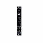
Doepfer A-138f Dual 3-Way Crossfader Slim Line Series Module (silver) (dual/stereo/mixer/panning synth module)
Cat: 847088 Rel: 09 Nov 21 • View all Synth modules
Dual Three-Way Crossfader (Slim Line Series)
Notes: Module A-138f contains two identical crossfaders with three inputs and one output each. Three different signals are connected to the inputs A, B and C. In the ccw position of the corresponding control only signal A appears at the output. Between ccw and center position a mix of the signals A and B appears at the output. In the center position only signal B appears at the output. Between center and cw position a mix of signals B and C appears at the output. In the cw position only signal C appears at the output.
The module is DC coupled and can be used for both audio and control voltage processing.
Application examples:
Crossfading of VCO waveforms (e.g. saw - rectangle - triangle)
Crossfading of VCF outputs of multimode filters (e.g. lowpass - notch - highpass - bandpass)
Crossfading of control voltage signals (e.g. envelope - LFO - random)
Width: 4 HP / 20.0 mm
Depth: 30 mm (measured from the rear side of the front panel)
Current: +10mA (+12V) / -10mA (-12V)
… Read moreThe module is DC coupled and can be used for both audio and control voltage processing.
Application examples:
Crossfading of VCO waveforms (e.g. saw - rectangle - triangle)
Crossfading of VCF outputs of multimode filters (e.g. lowpass - notch - highpass - bandpass)
Crossfading of control voltage signals (e.g. envelope - LFO - random)
Width: 4 HP / 20.0 mm
Depth: 30 mm (measured from the rear side of the front panel)
Current: +10mA (+12V) / -10mA (-12V)
out of stock $64.35
People also bought...
Doepfer A-149-4 Quad VC Random Polyphonic Random Voltage Source Slim Line Series Module (quad/random synth module)
Cat: 847089 Rel: 24 Jun 22 • View all Synth modules
Quad Random Voltage Source (Slim Line Series)
Notes: Module A-149-4 generates four triggered random voltages which meet the criteria choosen by several controls.
Manual controls for the criteria selection:
Octave range (manual control "Oct."): this parameter defines how many octaves are covered by the random voltages (0 ... +5V, with "Oct." control fully CCW only 0V are generated)
Grid (6 illuminated radio buttons): this parameter defines the grid of the random voltages:
Octaves (Oct)
Octaves + Quin (Quint)
Chords
Scale
Semitones
continuous (i.e. stepless)
Minor / Major (2 illuminated radio buttons): this parameter defines in case of chords or scales if they are minor or major. For all other grids this parameter has no meaning
Sixth / Seventh (2 illuminated separate buttons): these parameters defines if the sixth or seventh is added. Valid only if Oct, Quint, Chord or Scale is chosen as grid.
The output voltages follow the 1V/octave standard with exception of the Continuous mode. The voltages in this mode are totally random and do not follow the 1V/oct standard (i.e. not a multiple of 1/12V).
The generation of a new random voltage at the output (CV Out 1...4) is triggered by the corresponding trigger input (Trig. In 1...4). The trigger inputs are normalled top down. The minimum trigger level is +2.5V (up to max. +12V).
Applications:
random polyphonic structures (in combination with the polyphonic modules A-111-4, A-105-4, A-132-8, A-141-4 and e.g. A-157 as trigger source and A-173-1/2 for transposition of the polyphonic structures)
any application that requires several random voltages
Width: 4 HP / 20.0 mm
Depth: 45mm (measured from the rear side of the front panel)
… Read moreManual controls for the criteria selection:
Octave range (manual control "Oct."): this parameter defines how many octaves are covered by the random voltages (0 ... +5V, with "Oct." control fully CCW only 0V are generated)
Grid (6 illuminated radio buttons): this parameter defines the grid of the random voltages:
Octaves (Oct)
Octaves + Quin (Quint)
Chords
Scale
Semitones
continuous (i.e. stepless)
Minor / Major (2 illuminated radio buttons): this parameter defines in case of chords or scales if they are minor or major. For all other grids this parameter has no meaning
Sixth / Seventh (2 illuminated separate buttons): these parameters defines if the sixth or seventh is added. Valid only if Oct, Quint, Chord or Scale is chosen as grid.
The output voltages follow the 1V/octave standard with exception of the Continuous mode. The voltages in this mode are totally random and do not follow the 1V/oct standard (i.e. not a multiple of 1/12V).
The generation of a new random voltage at the output (CV Out 1...4) is triggered by the corresponding trigger input (Trig. In 1...4). The trigger inputs are normalled top down. The minimum trigger level is +2.5V (up to max. +12V).
Applications:
random polyphonic structures (in combination with the polyphonic modules A-111-4, A-105-4, A-132-8, A-141-4 and e.g. A-157 as trigger source and A-173-1/2 for transposition of the polyphonic structures)
any application that requires several random voltages
Width: 4 HP / 20.0 mm
Depth: 45mm (measured from the rear side of the front panel)
2 in stock $141.48

People also bought...
Doepfer A-182-4 Dual Rotary Switches Slim Line Series Module (dual/stereo/switch module)
Cat: 847091 Rel: 17 Nov 21 • View all Synth modules
Dual rotary switches module - 4HP
Notes: Module A-182-4 is a simple passive module that contains two mechanical rotary switches with 4 positions each. According to the position of the control knob socket 1, 2, 3 or 4 is connected to the common socket C.
As the module is fully passive it works bidirectional, i.e. the sockets 1...4 can be inputs and then C is the output. The other way round C can be the input and the sockets 1...4 are the outputs.
By means of an internal jumper the terminals C of both switches can be connected. That way the module can be used as kind of a miniature 4x4 matrix. Rotary switch A is e.g. used to select one of the four sockets 1...4 as input and this signal is sent to one of the four sockets 1...4 of switch B.
Applications:
switching of audio or control signals in the modular system without the need to unplug and plug patch cables (i.e. no signal interruptions)
building a small 4x4 miniature switch matrix
Width: 4 HP / 20.0 mm
Depth: 20mm (measured from the rear side of the front panel)
Current: 0mA (+12V) / 0mA (-12V)
… Read moreAs the module is fully passive it works bidirectional, i.e. the sockets 1...4 can be inputs and then C is the output. The other way round C can be the input and the sockets 1...4 are the outputs.
By means of an internal jumper the terminals C of both switches can be connected. That way the module can be used as kind of a miniature 4x4 matrix. Rotary switch A is e.g. used to select one of the four sockets 1...4 as input and this signal is sent to one of the four sockets 1...4 of switch B.
Applications:
switching of audio or control signals in the modular system without the need to unplug and plug patch cables (i.e. no signal interruptions)
building a small 4x4 miniature switch matrix
Width: 4 HP / 20.0 mm
Depth: 20mm (measured from the rear side of the front panel)
Current: 0mA (+12V) / 0mA (-12V)
out of stock $61.23
People also bought...
Cat: 828348 Rel: 15 Aug 18 • View all Synth modules
B-STOCK: Box opened, product in perfect working order
Notes: ***B-STOCK: Box opened, product in perfect working order***
Module A-199 is a spring reverb module. The reverb effect is electronically simulated by means of 3 spiral springs. Spring reverb systems have a very characteristic sound that is based on the (insufficient) mechanical properties of the springs like signal delays, audio resonances, limited frequency range, acoustic feedback behaviour, sensitivity to mechanical shocks and others.
The 3-spring system used in the A-199 ensures a "dense" reverb because of the different properties of the three springs.
The A-199 implies some special features that are not self-evident for spring reverb units:
The reverb signal can be fed back to the input using the Feedback control. Even self-oscillation of the springs similar to the self-oscillation of filters is available. The feedback loop can lead even via external modules like VCA, VCF, phaser, frequency shifter, vocoder, distortion/waveshaper, ring modulator and others. In this case the reverb output of the A-199 is connected to the input of the external module(s) and the output of the external module(s) is fed back to the Ext. Feedback In socket of the A-199. This socket contains a switch that interrupts the internal feedback loop as soon as a plug is inserted.
Another feature is the Emphasis control. This enables the adjustment of the accentuation of middle frequencies (around ~ 2kHz).
With the Mix control the relation between original and reverb signal appearing at the mix output is adjusted.
Using all these features very extreme and unusual effects can be generated with the A-199.
… Read moreModule A-199 is a spring reverb module. The reverb effect is electronically simulated by means of 3 spiral springs. Spring reverb systems have a very characteristic sound that is based on the (insufficient) mechanical properties of the springs like signal delays, audio resonances, limited frequency range, acoustic feedback behaviour, sensitivity to mechanical shocks and others.
The 3-spring system used in the A-199 ensures a "dense" reverb because of the different properties of the three springs.
The A-199 implies some special features that are not self-evident for spring reverb units:
The reverb signal can be fed back to the input using the Feedback control. Even self-oscillation of the springs similar to the self-oscillation of filters is available. The feedback loop can lead even via external modules like VCA, VCF, phaser, frequency shifter, vocoder, distortion/waveshaper, ring modulator and others. In this case the reverb output of the A-199 is connected to the input of the external module(s) and the output of the external module(s) is fed back to the Ext. Feedback In socket of the A-199. This socket contains a switch that interrupts the internal feedback loop as soon as a plug is inserted.
Another feature is the Emphasis control. This enables the adjustment of the accentuation of middle frequencies (around ~ 2kHz).
With the Mix control the relation between original and reverb signal appearing at the mix output is adjusted.
Using all these features very extreme and unusual effects can be generated with the A-199.
out of stock $93.82

People also bought...
Doepfer A-151v Quad Sequential Switch Vintage Edition Module (black) (B-STOCK) (quad/switch synth module)
Cat: 908477 Rel: 22 May 18 • View all Synth modules
B-STOCK: Box opened, product in perfect working order
Notes: ***B-STOCK: Box opened, product in perfect working order***
Module A-151 (Quad Sequential Switch) is like an electronic four-position rotary switch.
It includes trigger and reset inputs, four in/outputs, and a common out/input. Each time a pulse is received at the trigger input socket, the common out/input is connected to the next in/output. After the fourth in/output, the next trigger makes it step back to the first again, and so on. A positive pulse at the reset input switches the out/input immediately back to the first in/output. Voltages in the range -8V...+8V at the O/I resp. I/O sockets can be processed by the module.
Four LED's indicate the active in/output (ie. the one that is connected to the out/input at any particular time).
… Read moreModule A-151 (Quad Sequential Switch) is like an electronic four-position rotary switch.
It includes trigger and reset inputs, four in/outputs, and a common out/input. Each time a pulse is received at the trigger input socket, the common out/input is connected to the next in/output. After the fourth in/output, the next trigger makes it step back to the first again, and so on. A positive pulse at the reset input switches the out/input immediately back to the first in/output. Voltages in the range -8V...+8V at the O/I resp. I/O sockets can be processed by the module.
Four LED's indicate the active in/output (ie. the one that is connected to the out/input at any particular time).
out of stock $56.22

People also bought...
Doepfer A-141-2v VCADSR Voltage Controlled ADSR & LFO Module (vintage edition) (B-STOCK) (synth module)
Cat: 910924 Rel: 09 Jul 19 • View all Synth modules
B-STOCK: Box opened, product in perfect working order
Notes: ***B-STOCK: Box opened, product in perfect working order***
The A-141-2 module is an ADSR envelope generator with voltage controlled attack, decay, sustain and release parameters. Other features include LFO functionality as well as digital end-of-attack and end-of-release outputs. Besides positive and inverted outputs there is an output with voltage controlled amplitude available.
Attack, Decay, Sustain and Release parameters of the A-141-2 can be adjusted manually as well as via control voltages. The CV inputs come equipped with attenuators. In addition, a Comm-CV socket was implemented. Control voltages fed to this input influence all time parameters (A, D and R) simultaneously. Thus, it is possible to make high pitched notes shorter and more percussive. - Just like the behaviour of many acoustic instruments. The time range of the envelope goes from 50 microseconds to six seconds. Using a toggle switch, it is possible to increase these values by a factor of ten (500 us to 60 s) or a factor of hundred (5 ms to 10 min). To activate the envelope, there are gate and retrigger inputs.
The A-141-2 is equipped with a normal and an inverted output. Both connectors work with a fixed level. Furthermore, there is a third, variable output. Here, before reaching the out socket, the envelope signal is fed to a voltage controlled VCA. - Perfect for velocity CV signals. A jumper on the circuit board allows you to choose between a unipolar and a bipolar mode of operation. Other jumpers make it possible to normalize the CV inputs.
Last but not least, there are two digital outputs called EOA and EOR, which emit a gate signal after the attack respectively release phase. This is useful for delayed triggering of other envelopes. By connecting EOA or EOR output to the gate input, you can make the A-141-2 oscillate like a LFO. Adjustments to the envelope times change the frequency and waveform. If you connect the Attack CV input to the inverted output or the Decay respectively Release CV input to the normal output, you can alter the curve characteristics.
… Read moreThe A-141-2 module is an ADSR envelope generator with voltage controlled attack, decay, sustain and release parameters. Other features include LFO functionality as well as digital end-of-attack and end-of-release outputs. Besides positive and inverted outputs there is an output with voltage controlled amplitude available.
Attack, Decay, Sustain and Release parameters of the A-141-2 can be adjusted manually as well as via control voltages. The CV inputs come equipped with attenuators. In addition, a Comm-CV socket was implemented. Control voltages fed to this input influence all time parameters (A, D and R) simultaneously. Thus, it is possible to make high pitched notes shorter and more percussive. - Just like the behaviour of many acoustic instruments. The time range of the envelope goes from 50 microseconds to six seconds. Using a toggle switch, it is possible to increase these values by a factor of ten (500 us to 60 s) or a factor of hundred (5 ms to 10 min). To activate the envelope, there are gate and retrigger inputs.
The A-141-2 is equipped with a normal and an inverted output. Both connectors work with a fixed level. Furthermore, there is a third, variable output. Here, before reaching the out socket, the envelope signal is fed to a voltage controlled VCA. - Perfect for velocity CV signals. A jumper on the circuit board allows you to choose between a unipolar and a bipolar mode of operation. Other jumpers make it possible to normalize the CV inputs.
Last but not least, there are two digital outputs called EOA and EOR, which emit a gate signal after the attack respectively release phase. This is useful for delayed triggering of other envelopes. By connecting EOA or EOR output to the gate input, you can make the A-141-2 oscillate like a LFO. Adjustments to the envelope times change the frequency and waveform. If you connect the Attack CV input to the inverted output or the Decay respectively Release CV input to the normal output, you can alter the curve characteristics.
out of stock $108.69

People also bought...
Doepfer A-134-1 Voltage Controlled Panner & Crossfader Module (silver) (B-STOCK) (VCA/panning synth module)
Cat: 911640 Rel: 29 Jan 19 • View all Synth modules
B-STOCK: Box opened, product in perfect working order
Notes: ***B-STOCK: Box opened, product in perfect working order***
A-134-1 is a voltage controlled universal panning and/or crossfader module. If the module is used a voltage controlled Panning device one audio signal is panned to two different outputs. If the module is used a voltage controlled Crossfader two audio signals are mixed to one common output. The module enables even compositions of both functions.
The module contains two linear high quality VCAs (made with CEM3381/PA381 until April 2013, SSM2164 from May 2013). VCA2 works in the opposite direction of VCA1 i.e. the more VCA1's loudness increases the more VCA2's loudness decreases. The panning or crossfading is adjusted with a control knob (manual control) and by two external control voltages, one equipped with an attenuator. Suitable control voltage sources are e.g. LFOs (A-145, A-146, A-147), envelope signals (A-140, A-141, A-142, A-119), random (A-118), Theremin (A-178) or a voltage coming from a MIDI-to-CV-Interface (A-190, A-191). The panning/crossfading is displayed with 2 LEDs.
A-134-1 has an audio input with attenuator for each VCA. If the audio input of VCA2 is not used the audio input of VCA1 is connected with audio in of VCA 2, i.e. the sockets are "normalled". The module has three audio outputs: Left Output (VCA1), Right Output (VCA2) and Mix. For Panning applications the outputs Left Out and Right Out are used. If the module is used as a Crossfader the Mix Output functions as output.
Module A-134-1 enables voltage controlled stereophonic panning effects (one audio signal distributed to two outputs), crossfading effects (two audio inputs mixed to one audio output with voltage controlled loudness proportion) and combinations of both effects.
… Read moreA-134-1 is a voltage controlled universal panning and/or crossfader module. If the module is used a voltage controlled Panning device one audio signal is panned to two different outputs. If the module is used a voltage controlled Crossfader two audio signals are mixed to one common output. The module enables even compositions of both functions.
The module contains two linear high quality VCAs (made with CEM3381/PA381 until April 2013, SSM2164 from May 2013). VCA2 works in the opposite direction of VCA1 i.e. the more VCA1's loudness increases the more VCA2's loudness decreases. The panning or crossfading is adjusted with a control knob (manual control) and by two external control voltages, one equipped with an attenuator. Suitable control voltage sources are e.g. LFOs (A-145, A-146, A-147), envelope signals (A-140, A-141, A-142, A-119), random (A-118), Theremin (A-178) or a voltage coming from a MIDI-to-CV-Interface (A-190, A-191). The panning/crossfading is displayed with 2 LEDs.
A-134-1 has an audio input with attenuator for each VCA. If the audio input of VCA2 is not used the audio input of VCA1 is connected with audio in of VCA 2, i.e. the sockets are "normalled". The module has three audio outputs: Left Output (VCA1), Right Output (VCA2) and Mix. For Panning applications the outputs Left Out and Right Out are used. If the module is used as a Crossfader the Mix Output functions as output.
Module A-134-1 enables voltage controlled stereophonic panning effects (one audio signal distributed to two outputs), crossfading effects (two audio inputs mixed to one audio output with voltage controlled loudness proportion) and combinations of both effects.
out of stock $78.20

People also bought...
Doepfer A-126-2v Frequency Shifter Vintage Edition Module (black) (B-STOCK) (oscillator/phase shifter/pitch shifter/VCA synth module)
Cat: 912589 Rel: 17 Nov 21 • View all Synth modules
B-STOCK: Item refurbished, repaired and in perfect working order.
Notes: ***B-STOCK: Item refurbished, repaired and in perfect working order.***
'Vintage' black panel version of Doepfer's updated frequency shifter module, offering weird and wonderful effects by shifting all frequencies by a fixed amount. Unique sound, not to be confused with pitch shifting.
Supplier's Notes:
Module A-126-2 is a fully analog frequency shifter for audio signals. A frequency shifter is an audio processing unit that shifts each frequency of the incoming audio signal by the same frequency. If the shifting frequency is e.g. 200Hz an incoming audio frequency of 1000 Hz becomes 1200 Hz, 2000Hz becomes 2200 Hz, 3000 Hz becomes 3200 Hz and so on. Pay attention that this is different from pitch shifting where all frequencies are shifted proportional (e.g. 1000>1200Hz, 2000>2400Hz, 3000>3600Hz) !
The frequency range of the internal quadrature VCO is about 8 octaves (about 20Hz ... 5kHz). If required an external quadrature VCO can be used.
The module is equipped with these controls, inputs and outputs:
Frequ. 1: first manual control of the shifting frequency (factory setting: coarse, range about 20Hz - 5 kHz)
Frequ. 2: second manual control of the shifting frequency (factory setting: fine)
by means of internal jumpers the sensitivity of Frequ.1 and 2 can be swapped (i.e. Frequ.1 = fine and Frequ.2 = coarse)
the relation between coarse and fine control is about 25:1 (corresponding to about 8 octaves to 1/3 octave)
FCV In (socket) and FCV (small control without knob): control voltage input with attenuator for the external voltage control of the shifting frequency
Mix: manual control of the up/down shift panning unit, fully CCW = down shift, fully CW = up shift, in between a mixture of down and up
Mix CV In (socket) and Mix CV (small control without knob): control voltage input with attenuator for the mixing unit for external voltage control of the up/down mixing
Audio In (socket), Level (small control without knob) and Overload (LED): audio input with attenuator, typ. audio in level = 1Vpp, the level control has to be adjusted so that the overload LED just begins to light up a bit, when the LED is fully on clipping/distortion occurs, when the LED is permanently off the input level is too low and the signal-to-noise ratio increases
Audio Out (socket): audio output of the frequency shifter
Squelch (small control without knob): controls the squelch function: fully CCW (Env.) the output VCA is controlled by the envelope signal, which is derived from the audio input signal, fully CW (open) the output VCA is permanently open (no squelch function), in between the squelch intensity can be adjusted
Quadrature VCO Outputs (sockets Sin and Cos): outputs of the internal quadrature oscillator, about 12Vpp level (+6V/-6V)
Ext. Inputs Sin and Cos (sockets): required when an external quadrature VCO (e.g. A-143-9 with a wider frequency range or A-110-4 with thru zero feature or A-110-6 with different waveforms) is used instead of the internal quadrature VCO, the levels of the external VCO should be about 10Vpp (8...10Vpp are OK) and the signals have to be symmetrical around zero Volts, the sockets are normalled to the internal quadrature VCO (i.e. the sockets are equipped with switching contacts that interrupt the internal connection as soon as a plug inserted)
VCA ext. CV (socket): used when an external control voltage (e.g. from an envelope generator) should be used to control the output VCA instead of the internal squelch unit, the socket is normalled to the output of the squelch control (i.e. the socket is equipped with a switching contact that interrupts the internal squelch connection as soon as a plug inserted). From about +8V external control voltage the VCA is fully open.
Internal terminals (pin headers, e.g. for a DIY breakout module):
envelope follower output
dome filter output 1
dome filter output 2
ring modulator 1 output
ring modulator 2 output
Up shift output
Down shift output
… Read more'Vintage' black panel version of Doepfer's updated frequency shifter module, offering weird and wonderful effects by shifting all frequencies by a fixed amount. Unique sound, not to be confused with pitch shifting.
Supplier's Notes:
Module A-126-2 is a fully analog frequency shifter for audio signals. A frequency shifter is an audio processing unit that shifts each frequency of the incoming audio signal by the same frequency. If the shifting frequency is e.g. 200Hz an incoming audio frequency of 1000 Hz becomes 1200 Hz, 2000Hz becomes 2200 Hz, 3000 Hz becomes 3200 Hz and so on. Pay attention that this is different from pitch shifting where all frequencies are shifted proportional (e.g. 1000>1200Hz, 2000>2400Hz, 3000>3600Hz) !
The frequency range of the internal quadrature VCO is about 8 octaves (about 20Hz ... 5kHz). If required an external quadrature VCO can be used.
The module is equipped with these controls, inputs and outputs:
Frequ. 1: first manual control of the shifting frequency (factory setting: coarse, range about 20Hz - 5 kHz)
Frequ. 2: second manual control of the shifting frequency (factory setting: fine)
by means of internal jumpers the sensitivity of Frequ.1 and 2 can be swapped (i.e. Frequ.1 = fine and Frequ.2 = coarse)
the relation between coarse and fine control is about 25:1 (corresponding to about 8 octaves to 1/3 octave)
FCV In (socket) and FCV (small control without knob): control voltage input with attenuator for the external voltage control of the shifting frequency
Mix: manual control of the up/down shift panning unit, fully CCW = down shift, fully CW = up shift, in between a mixture of down and up
Mix CV In (socket) and Mix CV (small control without knob): control voltage input with attenuator for the mixing unit for external voltage control of the up/down mixing
Audio In (socket), Level (small control without knob) and Overload (LED): audio input with attenuator, typ. audio in level = 1Vpp, the level control has to be adjusted so that the overload LED just begins to light up a bit, when the LED is fully on clipping/distortion occurs, when the LED is permanently off the input level is too low and the signal-to-noise ratio increases
Audio Out (socket): audio output of the frequency shifter
Squelch (small control without knob): controls the squelch function: fully CCW (Env.) the output VCA is controlled by the envelope signal, which is derived from the audio input signal, fully CW (open) the output VCA is permanently open (no squelch function), in between the squelch intensity can be adjusted
Quadrature VCO Outputs (sockets Sin and Cos): outputs of the internal quadrature oscillator, about 12Vpp level (+6V/-6V)
Ext. Inputs Sin and Cos (sockets): required when an external quadrature VCO (e.g. A-143-9 with a wider frequency range or A-110-4 with thru zero feature or A-110-6 with different waveforms) is used instead of the internal quadrature VCO, the levels of the external VCO should be about 10Vpp (8...10Vpp are OK) and the signals have to be symmetrical around zero Volts, the sockets are normalled to the internal quadrature VCO (i.e. the sockets are equipped with switching contacts that interrupt the internal connection as soon as a plug inserted)
VCA ext. CV (socket): used when an external control voltage (e.g. from an envelope generator) should be used to control the output VCA instead of the internal squelch unit, the socket is normalled to the output of the squelch control (i.e. the socket is equipped with a switching contact that interrupts the internal squelch connection as soon as a plug inserted). From about +8V external control voltage the VCA is fully open.
Internal terminals (pin headers, e.g. for a DIY breakout module):
envelope follower output
dome filter output 1
dome filter output 2
ring modulator 1 output
ring modulator 2 output
Up shift output
Down shift output
out of stock $293.02
People also bought...
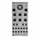
Doepfer A-121s Stereo Multimode Filter Module (silver) (dual/stereo/filter synth module)
Cat: 880248 Rel: 19 Aug 22 • View all Synth modules
Module A-121s is a dual multimode filter which can be used for stereo applications as well as for parallel or serial organized dual mono filters.
Notes: Module A-121s is a dual multimode filter which can be used for stereo applications as well as for parallel or serial organized dual mono filters. The core is a 12dB multimode filter identical to the modules A-121-2 and A-121-3. The selection of the filter type is continuously from lowpass via notch and highpass to bandpass. We attached great importance to the usability of the manual controls and CV inputs for both stereo and dual mono applications. For the filter parameters frequency (F), resonance (Q) and type (T) common controls and CV inputs as well as single controls and CV inputs are available. For the filter frequency in addition a manual control and CV input for the filter spread (frequency difference or delta F) is available.
Controls:
F: master frequency control for both filters (large knob)
Type 1 / Type 2: filter type panning/morphing L-N-H-B
Link to 1: Toggle switch so that Type 1 also controls type of filter 2 (i.e. simultaneous filter type control for both filters)
SFM1 / SFM2: Single Frequency Modulation controls (polarizers), connected to the corresponding sockets SFM1/SFM2 (socket SFM1 is normalled to a fixed positive voltage, SFM2 is normalled to SFM1, that way the controls SFM1/SFM2 work as frequency controls for each filter provided that no modulation signals are patched to the SFM1/SFM2 sockets)
CFM: common frequency control, controls two VC-polarizers which process the signals connected to the two sockets CFM1/CFM2, CFM2 is normalled to CFM1, that way also the same modulation signal (e.g. an envelope generator) can be used for both filters and the level controlled simultaneously by the CFM control
Delta F: controls the difference between the frequencies of the two filters manually (frequency "spread"), at centre position the frequencies are the same
Delta FM: controls the level of the Delta FM signal (socket), which allows to control the spread between the frequencies also by an external control voltage (e.g. by an LFO or ADSR)
Q: controls the resonance of both filters simultaneously
Level 1 / Level 2: attenuators for the two audio inputs
QM/TM1, QM/TM2: attenuators for the modulation inputs QM/TM1 and QM/TM2
Sockets:
In1 / In2: audio inputs (In2 is normalled to In1)
Out1 / Out2: audio outputs
F: common frequency control input for both filters (~ 1V/oct)
Delta FM: Control voltage for frequency spread, processed by the polarizer Delta FM
SFM1 / SFM2: single frequency modulation inputs, processed by the polarizers SFM1 and SFM2, SFM1 is normalled to a fixed positive voltage, SFM2 is normalled to SFM1#
CFM1 / CFM2: common frequency modulation inputs, processed by the two voltage controlled polarizers controlled by CFM knob, CFM2 is normalled to CFM1
QM/TM1, QM/TM2: the addressing of these sockets/attenuators is defined by internal jumpers. QM means Q modulation (i.e. resonance modulation), TM means filter type modulation (QM1 = resonance modulation filter 1, QM2 = resonance modulation filter 2, TM1 = filter type modulation filter 1, TM2 = filter type modulation filter 2), socket QM/TM1 is normalled to a fixed positive voltage, QM/TM2 is normalled to QM/TM1
A 45 degrees triangle next to a socket means that the switching contact of the socket is normalled to a fixed positive voltage (SFM1, QM/TM1).
A vertical triangle indicates the normalling of two sockets (In1>In2, SFM1>SFM2, CFM1>CFM2, QM/TM1>QM/TM2).
If the filters do not behave as expected please pay attention to these peculiarities:
For the controls SFM1, SFM2, CFM, Delta F and Delta FM the centre position is the neutral position as these are polarizers. If the filter behaves unexpected these controls should be set to centre positions for the time being.
For the controls F, Q, Level 1, Level 2, QM/TM1 und QM/TM2 the fully CCW position is the neutral position as these are standard attenuators. If the filter behaves unexpected at least the controls QM/TM1 and QM/TM2 should be set to fully CCW. Via the normalling of the sockets QM/TM1 and QM/TM2 and the associated controls the filter parameters adjusted by the major controls (e.g. Type 1, Type 2 or Q) may be overwritten.
By means of small circles at the bottom right side of the front panel the user can mark the function of the QM/TM inputs. These assignments are possible:
QM/TM1 controls QM1, QM/TM2 controls QM2, the filter types are not controlled by external CVs
QM/TM1 controls TM1, QM/TM2 controls TM2, the resonances are not controlled by external CVs
QM/TM1 controls QM1 and QM2 simultaneously, QM/TM2 controls TM1 and TM2 simultaneously
Depth: 45mm
HP : 12
… Read moreControls:
F: master frequency control for both filters (large knob)
Type 1 / Type 2: filter type panning/morphing L-N-H-B
Link to 1: Toggle switch so that Type 1 also controls type of filter 2 (i.e. simultaneous filter type control for both filters)
SFM1 / SFM2: Single Frequency Modulation controls (polarizers), connected to the corresponding sockets SFM1/SFM2 (socket SFM1 is normalled to a fixed positive voltage, SFM2 is normalled to SFM1, that way the controls SFM1/SFM2 work as frequency controls for each filter provided that no modulation signals are patched to the SFM1/SFM2 sockets)
CFM: common frequency control, controls two VC-polarizers which process the signals connected to the two sockets CFM1/CFM2, CFM2 is normalled to CFM1, that way also the same modulation signal (e.g. an envelope generator) can be used for both filters and the level controlled simultaneously by the CFM control
Delta F: controls the difference between the frequencies of the two filters manually (frequency "spread"), at centre position the frequencies are the same
Delta FM: controls the level of the Delta FM signal (socket), which allows to control the spread between the frequencies also by an external control voltage (e.g. by an LFO or ADSR)
Q: controls the resonance of both filters simultaneously
Level 1 / Level 2: attenuators for the two audio inputs
QM/TM1, QM/TM2: attenuators for the modulation inputs QM/TM1 and QM/TM2
Sockets:
In1 / In2: audio inputs (In2 is normalled to In1)
Out1 / Out2: audio outputs
F: common frequency control input for both filters (~ 1V/oct)
Delta FM: Control voltage for frequency spread, processed by the polarizer Delta FM
SFM1 / SFM2: single frequency modulation inputs, processed by the polarizers SFM1 and SFM2, SFM1 is normalled to a fixed positive voltage, SFM2 is normalled to SFM1#
CFM1 / CFM2: common frequency modulation inputs, processed by the two voltage controlled polarizers controlled by CFM knob, CFM2 is normalled to CFM1
QM/TM1, QM/TM2: the addressing of these sockets/attenuators is defined by internal jumpers. QM means Q modulation (i.e. resonance modulation), TM means filter type modulation (QM1 = resonance modulation filter 1, QM2 = resonance modulation filter 2, TM1 = filter type modulation filter 1, TM2 = filter type modulation filter 2), socket QM/TM1 is normalled to a fixed positive voltage, QM/TM2 is normalled to QM/TM1
A 45 degrees triangle next to a socket means that the switching contact of the socket is normalled to a fixed positive voltage (SFM1, QM/TM1).
A vertical triangle indicates the normalling of two sockets (In1>In2, SFM1>SFM2, CFM1>CFM2, QM/TM1>QM/TM2).
If the filters do not behave as expected please pay attention to these peculiarities:
For the controls SFM1, SFM2, CFM, Delta F and Delta FM the centre position is the neutral position as these are polarizers. If the filter behaves unexpected these controls should be set to centre positions for the time being.
For the controls F, Q, Level 1, Level 2, QM/TM1 und QM/TM2 the fully CCW position is the neutral position as these are standard attenuators. If the filter behaves unexpected at least the controls QM/TM1 and QM/TM2 should be set to fully CCW. Via the normalling of the sockets QM/TM1 and QM/TM2 and the associated controls the filter parameters adjusted by the major controls (e.g. Type 1, Type 2 or Q) may be overwritten.
By means of small circles at the bottom right side of the front panel the user can mark the function of the QM/TM inputs. These assignments are possible:
QM/TM1 controls QM1, QM/TM2 controls QM2, the filter types are not controlled by external CVs
QM/TM1 controls TM1, QM/TM2 controls TM2, the resonances are not controlled by external CVs
QM/TM1 controls QM1 and QM2 simultaneously, QM/TM2 controls TM1 and TM2 simultaneously
Depth: 45mm
HP : 12
2 in stock $233.52
People also bought...
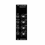
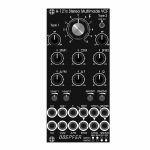
Doepfer A-121sV Stereo Multimode Filter Vintage Edition Module (black) (dual/stereo/filter synth module)
Cat: 880251 Rel: 18 Aug 22 • View all Synth modules
Module A-121s is a dual multimode filter which can be used for stereo applications as well as for parallel or serial organized dual mono filters.
Notes: Module A-121s is a dual multimode filter which can be used for stereo applications as well as for parallel or serial organized dual mono filters. The core is a 12dB multimode filter identical to the modules A-121-2 and A-121-3. The selection of the filter type is continuously from lowpass via notch and highpass to bandpass. We attached great importance to the usability of the manual controls and CV inputs for both stereo and dual mono applications. For the filter parameters frequency (F), resonance (Q) and type (T) common controls and CV inputs as well as single controls and CV inputs are available. For the filter frequency in addition a manual control and CV input for the filter spread (frequency difference or delta F) is available.
Controls:
F: master frequency control for both filters (large knob)
Type 1 / Type 2: filter type panning/morphing L-N-H-B
Link to 1: Toggle switch so that Type 1 also controls type of filter 2 (i.e. simultaneous filter type control for both filters)
SFM1 / SFM2: Single Frequency Modulation controls (polarizers), connected to the corresponding sockets SFM1/SFM2 (socket SFM1 is normalled to a fixed positive voltage, SFM2 is normalled to SFM1, that way the controls SFM1/SFM2 work as frequency controls for each filter provided that no modulation signals are patched to the SFM1/SFM2 sockets)
CFM: common frequency control, controls two VC-polarizers which process the signals connected to the two sockets CFM1/CFM2, CFM2 is normalled to CFM1, that way also the same modulation signal (e.g. an envelope generator) can be used for both filters and the level controlled simultaneously by the CFM control
Delta F: controls the difference between the frequencies of the two filters manually (frequency "spread"), at centre position the frequencies are the same
Delta FM: controls the level of the Delta FM signal (socket), which allows to control the spread between the frequencies also by an external control voltage (e.g. by an LFO or ADSR)
Q: controls the resonance of both filters simultaneously
Level 1 / Level 2: attenuators for the two audio inputs
QM/TM1, QM/TM2: attenuators for the modulation inputs QM/TM1 and QM/TM2
Sockets:
In1 / In2: audio inputs (In2 is normalled to In1)
Out1 / Out2: audio outputs
F: common frequency control input for both filters (~ 1V/oct)
Delta FM: Control voltage for frequency spread, processed by the polarizer Delta FM
SFM1 / SFM2: single frequency modulation inputs, processed by the polarizers SFM1 and SFM2, SFM1 is normalled to a fixed positive voltage, SFM2 is normalled to SFM1#
CFM1 / CFM2: common frequency modulation inputs, processed by the two voltage controlled polarizers controlled by CFM knob, CFM2 is normalled to CFM1
QM/TM1, QM/TM2: the addressing of these sockets/attenuators is defined by internal jumpers. QM means Q modulation (i.e. resonance modulation), TM means filter type modulation (QM1 = resonance modulation filter 1, QM2 = resonance modulation filter 2, TM1 = filter type modulation filter 1, TM2 = filter type modulation filter 2), socket QM/TM1 is normalled to a fixed positive voltage, QM/TM2 is normalled to QM/TM1
A 45 degrees triangle next to a socket means that the switching contact of the socket is normalled to a fixed positive voltage (SFM1, QM/TM1).
A vertical triangle indicates the normalling of two sockets (In1>In2, SFM1>SFM2, CFM1>CFM2, QM/TM1>QM/TM2).
If the filters do not behave as expected please pay attention to these peculiarities:
For the controls SFM1, SFM2, CFM, Delta F and Delta FM the centre position is the neutral position as these are polarizers. If the filter behaves unexpected these controls should be set to centre positions for the time being.
For the controls F, Q, Level 1, Level 2, QM/TM1 und QM/TM2 the fully CCW position is the neutral position as these are standard attenuators. If the filter behaves unexpected at least the controls QM/TM1 and QM/TM2 should be set to fully CCW. Via the normalling of the sockets QM/TM1 and QM/TM2 and the associated controls the filter parameters adjusted by the major controls (e.g. Type 1, Type 2 or Q) may be overwritten.
By means of small circles at the bottom right side of the front panel the user can mark the function of the QM/TM inputs. These assignments are possible:
QM/TM1 controls QM1, QM/TM2 controls QM2, the filter types are not controlled by external CVs
QM/TM1 controls TM1, QM/TM2 controls TM2, the resonances are not controlled by external CVs
QM/TM1 controls QM1 and QM2 simultaneously, QM/TM2 controls TM1 and TM2 simultaneously
… Read moreControls:
F: master frequency control for both filters (large knob)
Type 1 / Type 2: filter type panning/morphing L-N-H-B
Link to 1: Toggle switch so that Type 1 also controls type of filter 2 (i.e. simultaneous filter type control for both filters)
SFM1 / SFM2: Single Frequency Modulation controls (polarizers), connected to the corresponding sockets SFM1/SFM2 (socket SFM1 is normalled to a fixed positive voltage, SFM2 is normalled to SFM1, that way the controls SFM1/SFM2 work as frequency controls for each filter provided that no modulation signals are patched to the SFM1/SFM2 sockets)
CFM: common frequency control, controls two VC-polarizers which process the signals connected to the two sockets CFM1/CFM2, CFM2 is normalled to CFM1, that way also the same modulation signal (e.g. an envelope generator) can be used for both filters and the level controlled simultaneously by the CFM control
Delta F: controls the difference between the frequencies of the two filters manually (frequency "spread"), at centre position the frequencies are the same
Delta FM: controls the level of the Delta FM signal (socket), which allows to control the spread between the frequencies also by an external control voltage (e.g. by an LFO or ADSR)
Q: controls the resonance of both filters simultaneously
Level 1 / Level 2: attenuators for the two audio inputs
QM/TM1, QM/TM2: attenuators for the modulation inputs QM/TM1 and QM/TM2
Sockets:
In1 / In2: audio inputs (In2 is normalled to In1)
Out1 / Out2: audio outputs
F: common frequency control input for both filters (~ 1V/oct)
Delta FM: Control voltage for frequency spread, processed by the polarizer Delta FM
SFM1 / SFM2: single frequency modulation inputs, processed by the polarizers SFM1 and SFM2, SFM1 is normalled to a fixed positive voltage, SFM2 is normalled to SFM1#
CFM1 / CFM2: common frequency modulation inputs, processed by the two voltage controlled polarizers controlled by CFM knob, CFM2 is normalled to CFM1
QM/TM1, QM/TM2: the addressing of these sockets/attenuators is defined by internal jumpers. QM means Q modulation (i.e. resonance modulation), TM means filter type modulation (QM1 = resonance modulation filter 1, QM2 = resonance modulation filter 2, TM1 = filter type modulation filter 1, TM2 = filter type modulation filter 2), socket QM/TM1 is normalled to a fixed positive voltage, QM/TM2 is normalled to QM/TM1
A 45 degrees triangle next to a socket means that the switching contact of the socket is normalled to a fixed positive voltage (SFM1, QM/TM1).
A vertical triangle indicates the normalling of two sockets (In1>In2, SFM1>SFM2, CFM1>CFM2, QM/TM1>QM/TM2).
If the filters do not behave as expected please pay attention to these peculiarities:
For the controls SFM1, SFM2, CFM, Delta F and Delta FM the centre position is the neutral position as these are polarizers. If the filter behaves unexpected these controls should be set to centre positions for the time being.
For the controls F, Q, Level 1, Level 2, QM/TM1 und QM/TM2 the fully CCW position is the neutral position as these are standard attenuators. If the filter behaves unexpected at least the controls QM/TM1 and QM/TM2 should be set to fully CCW. Via the normalling of the sockets QM/TM1 and QM/TM2 and the associated controls the filter parameters adjusted by the major controls (e.g. Type 1, Type 2 or Q) may be overwritten.
By means of small circles at the bottom right side of the front panel the user can mark the function of the QM/TM inputs. These assignments are possible:
QM/TM1 controls QM1, QM/TM2 controls QM2, the filter types are not controlled by external CVs
QM/TM1 controls TM1, QM/TM2 controls TM2, the resonances are not controlled by external CVs
QM/TM1 controls QM1 and QM2 simultaneously, QM/TM2 controls TM1 and TM2 simultaneously
1 in stock $241.83

People also bought...
Doepfer A-183-5 Quad Attenuator Slim Line Series Module (silver) (attenuator/quad synth module)
Cat: 880264 Rel: 05 Oct 22 • View all Synth modules
Module A-183-5 is a simple passive quad attenuator.
Notes: Module A-183-5 is a simple passive quad attenuator. Passive means in this context, that each unit is made of two sockets and a 50k linear potentiometer only. There are no active parts like amplifiers or buffers and no power supply is required.
This is how the A-183-5 works: At the output socket appears the attenuated input signal, i.e. zero level at the fully CCW position and max. level and the fully CW position.
Applications:
Adjustable level of CV or audio signals to control other modules that do not have attenuators available.
Dimensions
4 HP
20 mm deep
… Read moreThis is how the A-183-5 works: At the output socket appears the attenuated input signal, i.e. zero level at the fully CCW position and max. level and the fully CW position.
Applications:
Adjustable level of CV or audio signals to control other modules that do not have attenuators available.
Dimensions
4 HP
20 mm deep
out of stock $69.54
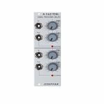
People also bought...
Doepfer A-162 Dual Trigger Delay Module (B-STOCK) (synth module)
Cat: 772513 Rel: 10 Sep 19 • View all Synth modules
B-STOCK: Item refurbished, repaired and in perfect working order.
Notes: ***B-STOCK: Item refurbished, repaired and in perfect working order.***
Module A-162 contains two identical circuits that generate a trigger signal with adjustable delay and length from an incoming rectangle signal (e.g. gate, trigger, rectangle output of an LFO or VCO). The rising edge of the incoming signal is used to trigger the new trigger signal. This module makes it possible to delay the onset of a trigger pulse, and also change its length.
On each of the two units, two controls can alter the onset time and duration of triggers, from about 2 ms up to more than 10 seconds. A control LED shows the generated signal.
… Read moreModule A-162 contains two identical circuits that generate a trigger signal with adjustable delay and length from an incoming rectangle signal (e.g. gate, trigger, rectangle output of an LFO or VCO). The rising edge of the incoming signal is used to trigger the new trigger signal. This module makes it possible to delay the onset of a trigger pulse, and also change its length.
On each of the two units, two controls can alter the onset time and duration of triggers, from about 2 ms up to more than 10 seconds. A control LED shows the generated signal.
out of stock $50.13

People also bought...
Cat: 846522 Rel: 15 Nov 19 • View all Synth modules
B-STOCK: Box opened, product in perfect working order
Notes: ***B-STOCK: Box opened, product in perfect working order***
Module A-188-1 is a so-called Bucket Brigade Device module.
BBDs have been used to delay audio signals before digital delays dethroned the BBD based effect units. But BBDs have some very unique advantages (or disadvantages dependent on the point of view) over the digital counterpart which result from the special properties of the BBDs. BBD circuits can be treated as a chain of Sample&Hold units (S&H) which pass on their voltages to the next S&H in the chain at each clock pulse.
In any case the sounds generated by module A-188-1 are very special. Typical applications are: Flanger, Chorus, Analog Delay or Karplus/Strong synthesis. But as the A-188-1 has a lot of very unique features (voltage controlled clock rate / delay time with extreme range, polarity switches for the CV inputs, feedback and BBD out/mix, clock and CV output of the high speed VCO, BBD clock input, feedback insert, feedback up to self-oscillation) a lot of unusual applications can be realized with the module (e.g. delay controlled by ADSR, envelope, random or sequencer with positive or negative effect).
The A-188-1 also has no built-in anti-aliasing filter in order not to limit the possibilities of the module. For this the CV out is intended.
This module comes without BBD circuit. The final adjustment is possible only with the BBD circuit used in the module. Electronic experience and measuring equipment (digital multi-meter, oscilloscope, frequency meter) are required.
… Read moreModule A-188-1 is a so-called Bucket Brigade Device module.
BBDs have been used to delay audio signals before digital delays dethroned the BBD based effect units. But BBDs have some very unique advantages (or disadvantages dependent on the point of view) over the digital counterpart which result from the special properties of the BBDs. BBD circuits can be treated as a chain of Sample&Hold units (S&H) which pass on their voltages to the next S&H in the chain at each clock pulse.
In any case the sounds generated by module A-188-1 are very special. Typical applications are: Flanger, Chorus, Analog Delay or Karplus/Strong synthesis. But as the A-188-1 has a lot of very unique features (voltage controlled clock rate / delay time with extreme range, polarity switches for the CV inputs, feedback and BBD out/mix, clock and CV output of the high speed VCO, BBD clock input, feedback insert, feedback up to self-oscillation) a lot of unusual applications can be realized with the module (e.g. delay controlled by ADSR, envelope, random or sequencer with positive or negative effect).
The A-188-1 also has no built-in anti-aliasing filter in order not to limit the possibilities of the module. For this the CV out is intended.
This module comes without BBD circuit. The final adjustment is possible only with the BBD circuit used in the module. Electronic experience and measuring equipment (digital multi-meter, oscilloscope, frequency meter) are required.
out of stock $79.43

People also bought...
Doepfer A-138bv Logarithmic Mixer Vintage Edition Module (B-STOCK) (attenuator/mixer synth module)
Cat: 888044 Rel: 29 Jan 19 • View all Synth modules
B-STOCK: Box opened, product in perfect working order
Notes: ***B-STOCK: Box opened, product in perfect working order***
Module A-138 is a four channel mixer, which can be used with either control voltages or audio signals. Each of the four inputs has an attenuator, and there's a master attenuator, so that the mixer can be used at the end of the audio chain - i.e. it can be used to interface directly with an external mixer, amplifier, etc.
A-138b features potentiometers with logarithmic response, so especially suitable for audio signal mixing.
Vintage Edition with a black faceplate and custom knobs.
… Read moreModule A-138 is a four channel mixer, which can be used with either control voltages or audio signals. Each of the four inputs has an attenuator, and there's a master attenuator, so that the mixer can be used at the end of the audio chain - i.e. it can be used to interface directly with an external mixer, amplifier, etc.
A-138b features potentiometers with logarithmic response, so especially suitable for audio signal mixing.
Vintage Edition with a black faceplate and custom knobs.
out of stock $65.36

People also bought...
Doepfer A-111-6v Miniature Synthesiser Voice Vintage Edition Module (black) (B-STOCK) (synth voice synth module)
Cat: 904371 Rel: 15 Nov 19 • View all Synth modules
B-STOCK: Slight surface marks
Notes: ***B-STOCK: Slight surface marks ***
VCO:
- Tune: manual tune control (with an internal jumper the range can be set to ~ +/-1 half an octave or ~ +/-2.5 octaves)
- Oct: range switch -1 / 0 / +1 octave
- Mod: modulation depth (attenuator wired to the Mod. socket)
- Dest: switch that is used to address the modulation to frequency modulation (position FM) or pulsewidth modulation (positon PM), in centre positon no modulation
- PW: manual pulsewidth control for rectangle waveform, PW can be also modulated by the Mod. input as mentioned above
- Wave: waveform switch (sawtooth / off / triangle), the sum of the waveform chosen by this switch and the rectangle is fed into the VCF (to turn the rectangle off the PW control has to be set fully CCW or fully CW)
- 1V/Oct. (socket): external CV input for VCO frequency (1V/octave)
- Access to internal bus CV (via jumper, optional, please remove the bus jumper if this feature is not used to avoid unwanted frequency modulation as then the unused CV line of the bus works as a kind of antenna)
- Triangle core VCO, frequency range about 32Hz ... 8kHz
Balance unit:
- The balance unit is made of two VCAs which are controlled by the sum of manual Balance control and the balance CV input in the opposite direction.
- The audio input of VCA1 is hard-wired to the VCO output, audio input 2 is connected to the socket Ext.In.
- The output of the balance unit is used as audio input for the VCF
- Bal.: manual balance control, fully CCW the internal VCO is used, fully CW the external signal (Ext.In) is used, at centre position both signals have about the same level
- CV Bal.: CV input for balance (range about 0...+5V)
- Ext. In: external audio input for VCA2, about 5 Vpp level required for similar loudness as the internal VCO
- This socket is normalled to the internal VCO suboctave f/2 signal (rectangle with half the frequency), if no external signal is applied the suboctave signal is used as the second signal for the balance unit
VCF:
- 24 dB low pass
- Frq: manual frequency control
- FM1: frequency modulation depth (attenuator wired to the VCF FM1 socket, the socket is normalled to the internal Envelope signal and then FM1 controls the modulation depth of the internal envelope applied to the filter)
- FM2 (socket) : second CV input for VCF without attenuator (about 1V/octave), can be used e.g. for VCF tracking by connecting the same CV which is used also for the VCO frequency
- Res: manual resonance control (up to self oscillation)
- If the VCO is turned off (waveform switch = centre position, pulsewidth control = fully CCW or CW) and the VCF resonance is set to maximum the module can be used as a sine oscillator, the tracking at socket VCF FM2 is about 1V/octave (not as precise as the VCO but much better than most other filters)
- ~ 11 octaves frequency range (~ 10 Hz ... 20kHz)
VCA:
- Gain: manual amplitude control (initial gain), can be used to open the VCA without envelope signal
- VCA (switch): used to switch between gate and envelope as control signal for the VCA, in centre position the VCA is not controlled by envelope or gate
- Note: when gate is used the VCA is controlled directly by the gate signal (i.e. hard on/off), this may lead to clicking noise under certain conditions (especially with low VCO/VCF frequencies)
- Special control scale: exponential scale in the range from about -20dB to -80/90dB, linear scale from about -20dB to 0dB
- Remark: this special control scale results in a loudness behaviour that is a bit different from pure linear or exponential VCAs
- Out: audio output of the module (= VCA output)
Envelope:
- Gate (socket): Gate input (min. +5V), can be normalled to the bus gate signal by means of a jumper
- Att: manual control for Attack
- D/R: manual control for Decay/Release
- Env. (switch): used to switch between A/D, ADSR and A/R mode of the envelope generator, in centre position (ADSR) the sustain level is fixed to about 50%
- Envelope (socket): envelope output (about +10V)
- CVT (socket): CV input for time control, by means of two internal jumpers one can select which time parameters are controlled by the CVT input (e.g. A only or D/R only or A/D/R) and in which direction (i.e. if an increasing CVT shortens or stretches the time parameter in question)
- Envelope LED display
- Attack time range: ~ 1ms ... 5 sec (can be extended by using the CVT input)
- Decay/Release time range: ~ 1ms ... 15 sec (can be extended by using the CVT input)
… Read moreVCO:
- Tune: manual tune control (with an internal jumper the range can be set to ~ +/-1 half an octave or ~ +/-2.5 octaves)
- Oct: range switch -1 / 0 / +1 octave
- Mod: modulation depth (attenuator wired to the Mod. socket)
- Dest: switch that is used to address the modulation to frequency modulation (position FM) or pulsewidth modulation (positon PM), in centre positon no modulation
- PW: manual pulsewidth control for rectangle waveform, PW can be also modulated by the Mod. input as mentioned above
- Wave: waveform switch (sawtooth / off / triangle), the sum of the waveform chosen by this switch and the rectangle is fed into the VCF (to turn the rectangle off the PW control has to be set fully CCW or fully CW)
- 1V/Oct. (socket): external CV input for VCO frequency (1V/octave)
- Access to internal bus CV (via jumper, optional, please remove the bus jumper if this feature is not used to avoid unwanted frequency modulation as then the unused CV line of the bus works as a kind of antenna)
- Triangle core VCO, frequency range about 32Hz ... 8kHz
Balance unit:
- The balance unit is made of two VCAs which are controlled by the sum of manual Balance control and the balance CV input in the opposite direction.
- The audio input of VCA1 is hard-wired to the VCO output, audio input 2 is connected to the socket Ext.In.
- The output of the balance unit is used as audio input for the VCF
- Bal.: manual balance control, fully CCW the internal VCO is used, fully CW the external signal (Ext.In) is used, at centre position both signals have about the same level
- CV Bal.: CV input for balance (range about 0...+5V)
- Ext. In: external audio input for VCA2, about 5 Vpp level required for similar loudness as the internal VCO
- This socket is normalled to the internal VCO suboctave f/2 signal (rectangle with half the frequency), if no external signal is applied the suboctave signal is used as the second signal for the balance unit
VCF:
- 24 dB low pass
- Frq: manual frequency control
- FM1: frequency modulation depth (attenuator wired to the VCF FM1 socket, the socket is normalled to the internal Envelope signal and then FM1 controls the modulation depth of the internal envelope applied to the filter)
- FM2 (socket) : second CV input for VCF without attenuator (about 1V/octave), can be used e.g. for VCF tracking by connecting the same CV which is used also for the VCO frequency
- Res: manual resonance control (up to self oscillation)
- If the VCO is turned off (waveform switch = centre position, pulsewidth control = fully CCW or CW) and the VCF resonance is set to maximum the module can be used as a sine oscillator, the tracking at socket VCF FM2 is about 1V/octave (not as precise as the VCO but much better than most other filters)
- ~ 11 octaves frequency range (~ 10 Hz ... 20kHz)
VCA:
- Gain: manual amplitude control (initial gain), can be used to open the VCA without envelope signal
- VCA (switch): used to switch between gate and envelope as control signal for the VCA, in centre position the VCA is not controlled by envelope or gate
- Note: when gate is used the VCA is controlled directly by the gate signal (i.e. hard on/off), this may lead to clicking noise under certain conditions (especially with low VCO/VCF frequencies)
- Special control scale: exponential scale in the range from about -20dB to -80/90dB, linear scale from about -20dB to 0dB
- Remark: this special control scale results in a loudness behaviour that is a bit different from pure linear or exponential VCAs
- Out: audio output of the module (= VCA output)
Envelope:
- Gate (socket): Gate input (min. +5V), can be normalled to the bus gate signal by means of a jumper
- Att: manual control for Attack
- D/R: manual control for Decay/Release
- Env. (switch): used to switch between A/D, ADSR and A/R mode of the envelope generator, in centre position (ADSR) the sustain level is fixed to about 50%
- Envelope (socket): envelope output (about +10V)
- CVT (socket): CV input for time control, by means of two internal jumpers one can select which time parameters are controlled by the CVT input (e.g. A only or D/R only or A/D/R) and in which direction (i.e. if an increasing CVT shortens or stretches the time parameter in question)
- Envelope LED display
- Attack time range: ~ 1ms ... 5 sec (can be extended by using the CVT input)
- Decay/Release time range: ~ 1ms ... 15 sec (can be extended by using the CVT input)
out of stock $170.76

People also bought...
Doepfer A-140v ADSR Envelope Generator Vintage Edition Module (black) (B-STOCK) (envelope generator synth module)
Cat: 904458 Rel: 10 Jul 19 • View all Synth modules
B-STOCK: Box opened, product in perfect working order
Notes: ***B-STOCK: Box opened, product in perfect working order***
Module A-140-1 is an envelope generator, and, since it puts out control voltages, counts as one of the modulation devices in a modular system. As soon as the gate input receives sufficient voltage, the ADSR generates a variable voltage, changing in time, called an envelope. This varying voltage is output in normal (positive) and inverted form, and can be used, eg. for voltage controlled modulation of a VCO, VCF, or VCA, or for processing other modules' inputs and outputs.
The shape of the envelope is governed by four parameters: Attack, Decay, Sustain and Release.
The envelope is started (triggered) by a gate signal either from the INT.GATE voltage on the system bus, or, if a signal is put into it, from the gate input socket.
The envelope can also be re-triggered, i.e. start from scratch again, each time a trigger signal is sensed at the Retrig. input socket, when the gate is still open.
Module A-140 has available a three-position toggle switch to select one of three time ranges. The time ratios for the three ranges are about 1 : 20 : 1000. The absolute Attack times are about:
20uS ... 100ms (switch position L)
400uS ... 2s (switch position M)
20ms ... 120s (switch position H)
The Decay and Release times are about 3-4 times more. Because of the exponential slope and the gradual asymptotic approach to the zero level the exact specification of the decay and real times is a bit difficult.
The voltage ranges of the ADSR outputs are about 0 ... +8V for the two normal outputs and 0 ... -8V for the inverted output.
In combination with the Comparator module A-167 a free-running "ADSR-LFO" can be realized.
… Read moreModule A-140-1 is an envelope generator, and, since it puts out control voltages, counts as one of the modulation devices in a modular system. As soon as the gate input receives sufficient voltage, the ADSR generates a variable voltage, changing in time, called an envelope. This varying voltage is output in normal (positive) and inverted form, and can be used, eg. for voltage controlled modulation of a VCO, VCF, or VCA, or for processing other modules' inputs and outputs.
The shape of the envelope is governed by four parameters: Attack, Decay, Sustain and Release.
The envelope is started (triggered) by a gate signal either from the INT.GATE voltage on the system bus, or, if a signal is put into it, from the gate input socket.
The envelope can also be re-triggered, i.e. start from scratch again, each time a trigger signal is sensed at the Retrig. input socket, when the gate is still open.
Module A-140 has available a three-position toggle switch to select one of three time ranges. The time ratios for the three ranges are about 1 : 20 : 1000. The absolute Attack times are about:
20uS ... 100ms (switch position L)
400uS ... 2s (switch position M)
20ms ... 120s (switch position H)
The Decay and Release times are about 3-4 times more. Because of the exponential slope and the gradual asymptotic approach to the zero level the exact specification of the decay and real times is a bit difficult.
The voltage ranges of the ADSR outputs are about 0 ... +8V for the two normal outputs and 0 ... -8V for the inverted output.
In combination with the Comparator module A-167 a free-running "ADSR-LFO" can be realized.
out of stock $83.39

People also bought...
Doepfer A-111-5v Mini Synthesiser Voice Vintage Edition Module (black) (envelope generator/filter/LFO/oscillator/synth voice/VCA synth module)
Cat: 671553 Rel: 18 Dec 17 • View all Synth modules
Complete monophonic synthesiser module - 24HP
Notes: Module A-111-5 is a complete monophonic synthesizer module that includes these components:
VCO
manual tune control (with an internal jumper the range can be set to ~ +/-1 half an octave or ~ +/-2.5 octaves)
range switch -1 / 0 / +1 octave
frequency range about 10Hz ... 12kHz
FM (frequency modulation) control with modulation source switch (LFO1 / off / ADSR)
manual pulsewidth control for rectangle waveform
PWM control with modulation source switch (LFO2 / off / ADSR)
waveform switch (sawtooth / off / triangle)
the sum of the waveform chosen by this switch and the rectangle is fed into the VCF (to turn the rectangle off the PW control has to be set fully CCW)
external CV input for VCO frequency (1V/octave)
external CV input for external PWM of the rectangle
internal CV input for frequency (1V/octave) connected to the A-100 bus via jumper, the jumper can be used to interrupt this internal connection if not wanted
VCF
24 dB low pass
~ 12 octaves frequency range
manual frequency control
tracking switch half - off - full (internally connected to the external frequency CV input of the VCO, i.e. the VCF tracks to the VCO if the switch is set to "half" or "full" position)
XM: exponential FM (frequency modulation) control with modulation source switch (LFO2 / off / ADSR)
LM: linear FM (frequency modulation) control to modulate the VCF by the triangle of the VCO in a linear (!) manner
manual resonance control (up to self oscillation)
external audio input (this signal is added to the VCO signal)
external CV input for filter frequency
1V/octave tracking for usage of the VCF as a sine wave oscillator (not as precise as the VCO but much better than most of the other filters)
VCA
manual amplitude control
AM (amplitude modulation) control with modulation source switch (LFO1 / off / ADSR)
external CV input for VCA amplitude
special control scale: exponential scale in the range from about -20dB to -80/90dB, linear scale from about -20dB to 0dB
Remark: this special control scale results in a loudness behaviour that is a bit different from pure linear or exponential VCAs
LFO1 and LFO2
manual frequency control
waveform switch (triangle / off / rectangle)
range switch (low, audio, medium)
LED display (dual green/red color for positive/negative share of the signal)
the inverted LFO1 signal is available as an additional socket (to use the LFO1 signal for external modules)
an internal jumper can be used to select between the LFO1 signal or the inverted LFO1 signal
ADSR
manual controls for Attack, Decay, Sustain, Release
range switch (long, short, medium)
blue LED display
ADSR signal is available as an additional socket (to use the ADSR signal for external modules)
Gate input connected to the A-100 bus via jumper, the jumper can be used to interrupt this internal connection if not wanted
Remarks:
As the LFO frequencies can go up to moderate audio range (~ 5kHz) even audio FM effects of VCO (pitch and pulsewidth), VCF and ADSR are possible !
If the VCO is turned off (waveform switch = center position, pulsewidth control = fully CCW) and the VCF resonance is set to maximum the module can be used as a sine oscillator. The sine can be modulated in a linear manner from the triangle wave of the VCO and by LFO2 in an exponential manner at the same time !
from the factory the socket labelled "LFO1" outputs the inverted LFO1 signal. But as the module has several internal pin headers available even another signal may appear at this socket by changing the internal module patch. These six pin headers are available: LFO1 output, LFO2 output, ADSR output, inverter input, inverter output, output socket. The internal default patch is LFO1 -> inverter input, inverter output -> output socket (i.e. socket = inverted LFO1). But even another signal can be patched to this socket (e.g. inverted ADSR, non-inverted LFO1, inverted or non-inverted LFO2). It is also possible to add a blind panel next to the A-111-5 with a couple of sockets that are connected to the corresponding pins of the A-111-5 pc board. The in- and outputs of the VCO, VCF and VCA are not available as pin headers because the VCO, VCF and VCA are internally connected in the circuit which is used in this module.
Dimensions
24 HP
40 mm deep
Current Draw
80 mA +12V
50 mA -12V
… Read moreVCO
manual tune control (with an internal jumper the range can be set to ~ +/-1 half an octave or ~ +/-2.5 octaves)
range switch -1 / 0 / +1 octave
frequency range about 10Hz ... 12kHz
FM (frequency modulation) control with modulation source switch (LFO1 / off / ADSR)
manual pulsewidth control for rectangle waveform
PWM control with modulation source switch (LFO2 / off / ADSR)
waveform switch (sawtooth / off / triangle)
the sum of the waveform chosen by this switch and the rectangle is fed into the VCF (to turn the rectangle off the PW control has to be set fully CCW)
external CV input for VCO frequency (1V/octave)
external CV input for external PWM of the rectangle
internal CV input for frequency (1V/octave) connected to the A-100 bus via jumper, the jumper can be used to interrupt this internal connection if not wanted
VCF
24 dB low pass
~ 12 octaves frequency range
manual frequency control
tracking switch half - off - full (internally connected to the external frequency CV input of the VCO, i.e. the VCF tracks to the VCO if the switch is set to "half" or "full" position)
XM: exponential FM (frequency modulation) control with modulation source switch (LFO2 / off / ADSR)
LM: linear FM (frequency modulation) control to modulate the VCF by the triangle of the VCO in a linear (!) manner
manual resonance control (up to self oscillation)
external audio input (this signal is added to the VCO signal)
external CV input for filter frequency
1V/octave tracking for usage of the VCF as a sine wave oscillator (not as precise as the VCO but much better than most of the other filters)
VCA
manual amplitude control
AM (amplitude modulation) control with modulation source switch (LFO1 / off / ADSR)
external CV input for VCA amplitude
special control scale: exponential scale in the range from about -20dB to -80/90dB, linear scale from about -20dB to 0dB
Remark: this special control scale results in a loudness behaviour that is a bit different from pure linear or exponential VCAs
LFO1 and LFO2
manual frequency control
waveform switch (triangle / off / rectangle)
range switch (low, audio, medium)
LED display (dual green/red color for positive/negative share of the signal)
the inverted LFO1 signal is available as an additional socket (to use the LFO1 signal for external modules)
an internal jumper can be used to select between the LFO1 signal or the inverted LFO1 signal
ADSR
manual controls for Attack, Decay, Sustain, Release
range switch (long, short, medium)
blue LED display
ADSR signal is available as an additional socket (to use the ADSR signal for external modules)
Gate input connected to the A-100 bus via jumper, the jumper can be used to interrupt this internal connection if not wanted
Remarks:
As the LFO frequencies can go up to moderate audio range (~ 5kHz) even audio FM effects of VCO (pitch and pulsewidth), VCF and ADSR are possible !
If the VCO is turned off (waveform switch = center position, pulsewidth control = fully CCW) and the VCF resonance is set to maximum the module can be used as a sine oscillator. The sine can be modulated in a linear manner from the triangle wave of the VCO and by LFO2 in an exponential manner at the same time !
from the factory the socket labelled "LFO1" outputs the inverted LFO1 signal. But as the module has several internal pin headers available even another signal may appear at this socket by changing the internal module patch. These six pin headers are available: LFO1 output, LFO2 output, ADSR output, inverter input, inverter output, output socket. The internal default patch is LFO1 -> inverter input, inverter output -> output socket (i.e. socket = inverted LFO1). But even another signal can be patched to this socket (e.g. inverted ADSR, non-inverted LFO1, inverted or non-inverted LFO2). It is also possible to add a blind panel next to the A-111-5 with a couple of sockets that are connected to the corresponding pins of the A-111-5 pc board. The in- and outputs of the VCO, VCF and VCA are not available as pin headers because the VCO, VCF and VCA are internally connected in the circuit which is used in this module.
Dimensions
24 HP
40 mm deep
Current Draw
80 mA +12V
50 mA -12V
out of stock $290.29

People also bought...
Doepfer A-106-5 SEM 12dB SEM Type VCF Module (silver) (B-STOCK) (filter synth module)
Cat: 935425 Rel: 06 Jun 19 • View all Synth modules
B-STOCK: Item refurbished, repaired and in perfect working order.
Notes: ***B-STOCK: Item refurbished, repaired and in perfect working order.***
Module A-106-5 is a 12dB multimode filter that is based on the filter circuit of the Oberheim SEM module.
The filter is equipped with a band pass output and a combined low/notch/high pass output. For this output a control knob defines the relation between low and high pass signal. If both signals appear at the same level (i.e. middle position of the Mix knob) one obtains a notch filter. Otherwise the low or high pass signal predominates.
The module does not feature self-oscillation in contrast to most of the other filters of the A-100 system.
The module generates a distorted audio signal if the level control is set to about 50% (i.e. centre position) or more with A-100 standard signals like VCOs.
… Read moreModule A-106-5 is a 12dB multimode filter that is based on the filter circuit of the Oberheim SEM module.
The filter is equipped with a band pass output and a combined low/notch/high pass output. For this output a control knob defines the relation between low and high pass signal. If both signals appear at the same level (i.e. middle position of the Mix knob) one obtains a notch filter. Otherwise the low or high pass signal predominates.
The module does not feature self-oscillation in contrast to most of the other filters of the A-100 system.
The module generates a distorted audio signal if the level control is set to about 50% (i.e. centre position) or more with A-100 standard signals like VCOs.
out of stock $76.01

People also bought...
Cat: 919015 Rel: 20 Dec 18 • View all Synth modules
B-STOCK: Product has light surface marks/scratches, but otherwise in perfect working condition
Notes: ***B-STOCK: Product has light surface marks/scratches, but otherwise in perfect working condition***
Module A-190-5 is a four voice Midi/USB to CV/Gate interface. For each voice a pitch control voltage (CV1, 1V/octave standard to control VCOs), a gate output (to control envelope generators) and two additional control voltages (CV2, CV3) are available. The two additional CV outputs can be controlled by Midi velocity, volume, modulation, pitch bend, after touch or free assignable Midi controllers.
- Four voice monophonic (i.e. to control four monophonic voices by four succeeding Midi channels)
- Four voice polyphonic (i.e. to control four monophonic voices by one Midi channel) with several sub-modes (e.g. rotating/non-rotating)
- Two voice polyphonic (i.e. to control two monophonic voices by one Midi channel)
- Unisono
The basic mode is selected by means of a momentary switch (probably Mode or Algor.) and is shown in the LC display. Certain parameters of each mode can be edited (e.g. the midi channel(s), the midi reference note for 0V CV, assigned controllers for CV2 and CV3). For this the momentary switch Edit/Play is used. The parameter values (e.g. midi channels) are shown in the display and can be modified by means of the momentary switches 1...4. In Play mode the LEDs of these four switches display the gate states.
… Read moreModule A-190-5 is a four voice Midi/USB to CV/Gate interface. For each voice a pitch control voltage (CV1, 1V/octave standard to control VCOs), a gate output (to control envelope generators) and two additional control voltages (CV2, CV3) are available. The two additional CV outputs can be controlled by Midi velocity, volume, modulation, pitch bend, after touch or free assignable Midi controllers.
- Four voice monophonic (i.e. to control four monophonic voices by four succeeding Midi channels)
- Four voice polyphonic (i.e. to control four monophonic voices by one Midi channel) with several sub-modes (e.g. rotating/non-rotating)
- Two voice polyphonic (i.e. to control two monophonic voices by one Midi channel)
- Unisono
The basic mode is selected by means of a momentary switch (probably Mode or Algor.) and is shown in the LC display. Certain parameters of each mode can be edited (e.g. the midi channel(s), the midi reference note for 0V CV, assigned controllers for CV2 and CV3). For this the momentary switch Edit/Play is used. The parameter values (e.g. midi channels) are shown in the display and can be modified by means of the momentary switches 1...4. In Play mode the LEDs of these four switches display the gate states.
out of stock $233.68
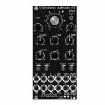
People also bought...
Doepfer A-121sV Stereo Multimode Filter Vintage Edition Module (black) (B-STOCK) (dual/stereo/filter synth module)
Cat: 924238 Rel: 01 Jan 90 • View all Synth modules
B-STOCK: Box opened, but product is in excellent condition and in perfect working order
Notes: ***B-STOCK: Box opened, but product is in excellent condition and in perfect working order***
Module A-121s is a dual multimode filter which can be used for stereo applications as well as for parallel or serial organized dual mono filters. The core is a 12dB multimode filter identical to the modules A-121-2 and A-121-3. The selection of the filter type is continuously from lowpass via notch and highpass to bandpass. We attached great importance to the usability of the manual controls and CV inputs for both stereo and dual mono applications. For the filter parameters frequency (F), resonance (Q) and type (T) common controls and CV inputs as well as single controls and CV inputs are available. For the filter frequency in addition a manual control and CV input for the filter spread (frequency difference or delta F) is available.
Controls:
F: master frequency control for both filters (large knob)
Type 1 / Type 2: filter type panning/morphing L-N-H-B
Link to 1: Toggle switch so that Type 1 also controls type of filter 2 (i.e. simultaneous filter type control for both filters)
SFM1 / SFM2: Single Frequency Modulation controls (polarizers), connected to the corresponding sockets SFM1/SFM2 (socket SFM1 is normalled to a fixed positive voltage, SFM2 is normalled to SFM1, that way the controls SFM1/SFM2 work as frequency controls for each filter provided that no modulation signals are patched to the SFM1/SFM2 sockets)
CFM: common frequency control, controls two VC-polarizers which process the signals connected to the two sockets CFM1/CFM2, CFM2 is normalled to CFM1, that way also the same modulation signal (e.g. an envelope generator) can be used for both filters and the level controlled simultaneously by the CFM control
Delta F: controls the difference between the frequencies of the two filters manually (frequency "spread"), at centre position the frequencies are the same
Delta FM: controls the level of the Delta FM signal (socket), which allows to control the spread between the frequencies also by an external control voltage (e.g. by an LFO or ADSR)
Q: controls the resonance of both filters simultaneously
Level 1 / Level 2: attenuators for the two audio inputs
QM/TM1, QM/TM2: attenuators for the modulation inputs QM/TM1 and QM/TM2
Sockets:
In1 / In2: audio inputs (In2 is normalled to In1)
Out1 / Out2: audio outputs
F: common frequency control input for both filters (~ 1V/oct)
Delta FM: Control voltage for frequency spread, processed by the polarizer Delta FM
SFM1 / SFM2: single frequency modulation inputs, processed by the polarizers SFM1 and SFM2, SFM1 is normalled to a fixed positive voltage, SFM2 is normalled to SFM1#
CFM1 / CFM2: common frequency modulation inputs, processed by the two voltage controlled polarizers controlled by CFM knob, CFM2 is normalled to CFM1
QM/TM1, QM/TM2: the addressing of these sockets/attenuators is defined by internal jumpers. QM means Q modulation (i.e. resonance modulation), TM means filter type modulation (QM1 = resonance modulation filter 1, QM2 = resonance modulation filter 2, TM1 = filter type modulation filter 1, TM2 = filter type modulation filter 2), socket QM/TM1 is normalled to a fixed positive voltage, QM/TM2 is normalled to QM/TM1
A 45 degrees triangle next to a socket means that the switching contact of the socket is normalled to a fixed positive voltage (SFM1, QM/TM1).
A vertical triangle indicates the normalling of two sockets (In1>In2, SFM1>SFM2, CFM1>CFM2, QM/TM1>QM/TM2).
If the filters do not behave as expected please pay attention to these peculiarities:
For the controls SFM1, SFM2, CFM, Delta F and Delta FM the centre position is the neutral position as these are polarizers. If the filter behaves unexpected these controls should be set to centre positions for the time being.
For the controls F, Q, Level 1, Level 2, QM/TM1 und QM/TM2 the fully CCW position is the neutral position as these are standard attenuators. If the filter behaves unexpected at least the controls QM/TM1 and QM/TM2 should be set to fully CCW. Via the normalling of the sockets QM/TM1 and QM/TM2 and the associated controls the filter parameters adjusted by the major controls (e.g. Type 1, Type 2 or Q) may be overwritten.
By means of small circles at the bottom right side of the front panel the user can mark the function of the QM/TM inputs. These assignments are possible:
QM/TM1 controls QM1, QM/TM2 controls QM2, the filter types are not controlled by external CVs
QM/TM1 controls TM1, QM/TM2 controls TM2, the resonances are not controlled by external CVs
QM/TM1 controls QM1 and QM2 simultaneously, QM/TM2 controls TM1 and TM2 simultaneously
… Read moreModule A-121s is a dual multimode filter which can be used for stereo applications as well as for parallel or serial organized dual mono filters. The core is a 12dB multimode filter identical to the modules A-121-2 and A-121-3. The selection of the filter type is continuously from lowpass via notch and highpass to bandpass. We attached great importance to the usability of the manual controls and CV inputs for both stereo and dual mono applications. For the filter parameters frequency (F), resonance (Q) and type (T) common controls and CV inputs as well as single controls and CV inputs are available. For the filter frequency in addition a manual control and CV input for the filter spread (frequency difference or delta F) is available.
Controls:
F: master frequency control for both filters (large knob)
Type 1 / Type 2: filter type panning/morphing L-N-H-B
Link to 1: Toggle switch so that Type 1 also controls type of filter 2 (i.e. simultaneous filter type control for both filters)
SFM1 / SFM2: Single Frequency Modulation controls (polarizers), connected to the corresponding sockets SFM1/SFM2 (socket SFM1 is normalled to a fixed positive voltage, SFM2 is normalled to SFM1, that way the controls SFM1/SFM2 work as frequency controls for each filter provided that no modulation signals are patched to the SFM1/SFM2 sockets)
CFM: common frequency control, controls two VC-polarizers which process the signals connected to the two sockets CFM1/CFM2, CFM2 is normalled to CFM1, that way also the same modulation signal (e.g. an envelope generator) can be used for both filters and the level controlled simultaneously by the CFM control
Delta F: controls the difference between the frequencies of the two filters manually (frequency "spread"), at centre position the frequencies are the same
Delta FM: controls the level of the Delta FM signal (socket), which allows to control the spread between the frequencies also by an external control voltage (e.g. by an LFO or ADSR)
Q: controls the resonance of both filters simultaneously
Level 1 / Level 2: attenuators for the two audio inputs
QM/TM1, QM/TM2: attenuators for the modulation inputs QM/TM1 and QM/TM2
Sockets:
In1 / In2: audio inputs (In2 is normalled to In1)
Out1 / Out2: audio outputs
F: common frequency control input for both filters (~ 1V/oct)
Delta FM: Control voltage for frequency spread, processed by the polarizer Delta FM
SFM1 / SFM2: single frequency modulation inputs, processed by the polarizers SFM1 and SFM2, SFM1 is normalled to a fixed positive voltage, SFM2 is normalled to SFM1#
CFM1 / CFM2: common frequency modulation inputs, processed by the two voltage controlled polarizers controlled by CFM knob, CFM2 is normalled to CFM1
QM/TM1, QM/TM2: the addressing of these sockets/attenuators is defined by internal jumpers. QM means Q modulation (i.e. resonance modulation), TM means filter type modulation (QM1 = resonance modulation filter 1, QM2 = resonance modulation filter 2, TM1 = filter type modulation filter 1, TM2 = filter type modulation filter 2), socket QM/TM1 is normalled to a fixed positive voltage, QM/TM2 is normalled to QM/TM1
A 45 degrees triangle next to a socket means that the switching contact of the socket is normalled to a fixed positive voltage (SFM1, QM/TM1).
A vertical triangle indicates the normalling of two sockets (In1>In2, SFM1>SFM2, CFM1>CFM2, QM/TM1>QM/TM2).
If the filters do not behave as expected please pay attention to these peculiarities:
For the controls SFM1, SFM2, CFM, Delta F and Delta FM the centre position is the neutral position as these are polarizers. If the filter behaves unexpected these controls should be set to centre positions for the time being.
For the controls F, Q, Level 1, Level 2, QM/TM1 und QM/TM2 the fully CCW position is the neutral position as these are standard attenuators. If the filter behaves unexpected at least the controls QM/TM1 and QM/TM2 should be set to fully CCW. Via the normalling of the sockets QM/TM1 and QM/TM2 and the associated controls the filter parameters adjusted by the major controls (e.g. Type 1, Type 2 or Q) may be overwritten.
By means of small circles at the bottom right side of the front panel the user can mark the function of the QM/TM inputs. These assignments are possible:
QM/TM1 controls QM1, QM/TM2 controls QM2, the filter types are not controlled by external CVs
QM/TM1 controls TM1, QM/TM2 controls TM2, the resonances are not controlled by external CVs
QM/TM1 controls QM1 and QM2 simultaneously, QM/TM2 controls TM1 and TM2 simultaneously
1 in stock $217.24

People also bought...
Doepfer A-185-2 Precision Adder/Bus Access Module (silver) (B-STOCK) (multiple/attenuator/mixer/utility/controller/switch synth module)
Cat: 924823 Rel: 23 Oct 19 • View all Synth modules
B-STOCK: Item refurbished, repaired and in perfect working order.
Notes: ***B-STOCK: Item refurbished, repaired and in perfect working order.***
Module A-185-2 is a precision control voltage adder/buffer. Precision means that the amplification of the inputs without attenuators is exactly 1.00 and is suitable to add control voltages for the pitch control of VCOs (e.g. from keyboard + sequencer 1 + sequencer 2). Summing resistors matched to 0.1% are used to obtain an accuracy of 0.1% for the added voltages.
The module is equipped with four CV inputs: one with attenuator and three without attenuator. Each input is normalled to +1 V (i.e. if no plug is inserted the input contributes 1 V to the sum appearing at the output).
The input with attenuator can be used for common modulations (e.g. from an LFO, ADSR, Theremin, Pitch-Bender) for all VCOs connected to the output. The Lev.1 control is used to adjust the depth of the modulation, the first switch selects the polarity of the modulation. If no signal is connected to the first socket the attenuator works as a (fine) tuning knob because a voltage in the range 0...+1V (right position of the switch) or 0...-1V (left position of the switch) is added to the CV output.
The inputs without attenuators are planned to add control voltages coming out of keyboards, sequencers, Midi-to-CV interfaces, ribbon controllers or other CV sources that follow the 1V/oct standard. For example the CV of a keyboard can be used to transpose the CV coming from a sequencer, or the CV of a slow sequencer can be used to transpose the CV from a fast sequencer.
Each input is equipped with a three-position switch that determines if the corresponding voltage is added (right position), subtracted (left position) or if the input has no effect (centre position). If no plug is inserted the corresponding switch works as an octave switch for the lower three sections as the default 1 V are added or subtracted to the output voltage according to the switch position. The first switch can be used to add a variable voltage to the sum output. The variable voltage is adjusted with the Lev.1 control and the knob works then as kind of a (fine) tuning control.
The module is equipped with 4 outputs: three non-inverting and one inverting ouput. An internal jumper can be used to connect the non-inverted or inverted output to the CV line of the A-100 bus. That way the module can used to control several VCOs that are connected to the same bus board as the A-185-2 (same functionality as A-185-1).
… Read moreModule A-185-2 is a precision control voltage adder/buffer. Precision means that the amplification of the inputs without attenuators is exactly 1.00 and is suitable to add control voltages for the pitch control of VCOs (e.g. from keyboard + sequencer 1 + sequencer 2). Summing resistors matched to 0.1% are used to obtain an accuracy of 0.1% for the added voltages.
The module is equipped with four CV inputs: one with attenuator and three without attenuator. Each input is normalled to +1 V (i.e. if no plug is inserted the input contributes 1 V to the sum appearing at the output).
The input with attenuator can be used for common modulations (e.g. from an LFO, ADSR, Theremin, Pitch-Bender) for all VCOs connected to the output. The Lev.1 control is used to adjust the depth of the modulation, the first switch selects the polarity of the modulation. If no signal is connected to the first socket the attenuator works as a (fine) tuning knob because a voltage in the range 0...+1V (right position of the switch) or 0...-1V (left position of the switch) is added to the CV output.
The inputs without attenuators are planned to add control voltages coming out of keyboards, sequencers, Midi-to-CV interfaces, ribbon controllers or other CV sources that follow the 1V/oct standard. For example the CV of a keyboard can be used to transpose the CV coming from a sequencer, or the CV of a slow sequencer can be used to transpose the CV from a fast sequencer.
Each input is equipped with a three-position switch that determines if the corresponding voltage is added (right position), subtracted (left position) or if the input has no effect (centre position). If no plug is inserted the corresponding switch works as an octave switch for the lower three sections as the default 1 V are added or subtracted to the output voltage according to the switch position. The first switch can be used to add a variable voltage to the sum output. The variable voltage is adjusted with the Lev.1 control and the knob works then as kind of a (fine) tuning control.
The module is equipped with 4 outputs: three non-inverting and one inverting ouput. An internal jumper can be used to connect the non-inverted or inverted output to the CV line of the A-100 bus. That way the module can used to control several VCOs that are connected to the same bus board as the A-185-2 (same functionality as A-185-1).
out of stock $65.09
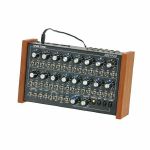
People also bought...
Doepfer Dark Time MIDI/USB Analogue Sequencer (white & blue LED version, supplied with 2 pin Euro plug) (B-STOCK) (MIDI/USB sequencer)
Cat: 926156 Rel: 01 Jan 90 • View all Sequencers
B-STOCK: Original box damaged, product is in different packagaing but is in perfect working order
Notes: ***B-STOCK: Original box damaged, product is in different packagaing but is in perfect working order***
Iconic analogue step sequencer from modular innovators Doepfer. Compatible with all MIDI or CV/gate synths, allowing a huge range of programming and sequencing options, plus real-time tweaking. A firm Juno favourite.
Supplier's notes:
Dark Time is an 2x8 step analogue sequencer with CV/Gate, USB and MIDI interface. It is intended as an add-on for the Dark Energy but may be used in combination with other MIDI, USB or CV/Gate equipment too.
… Read moreIconic analogue step sequencer from modular innovators Doepfer. Compatible with all MIDI or CV/gate synths, allowing a huge range of programming and sequencing options, plus real-time tweaking. A firm Juno favourite.
Supplier's notes:
Dark Time is an 2x8 step analogue sequencer with CV/Gate, USB and MIDI interface. It is intended as an add-on for the Dark Energy but may be used in combination with other MIDI, USB or CV/Gate equipment too.
out of stock $441.32
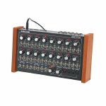
People also bought...
Doepfer Dark Time MIDI/USB Analogue Sequencer (red LED version, supplied with 2 pin Euro plug) (B-STOCK) (MIDI/USB sequencer)
Cat: 926166 Rel: 01 Jan 90 • View all Sequencers
B-STOCK: Original box damaged, product is in different packagaing but in perfect working order
Notes: ***B-STOCK: Original box damaged, product is in different packagaing but in perfect working order***
Dark Time is an 2x8 step analogue sequencer with CV/Gate, USB and MIDI interface. It is intended as an add-on for the Dark Energy but may be used in combination with other MIDI, USB or CV/Gate equipment too.
… Read moreDark Time is an 2x8 step analogue sequencer with CV/Gate, USB and MIDI interface. It is intended as an add-on for the Dark Energy but may be used in combination with other MIDI, USB or CV/Gate equipment too.
out of stock $365.77
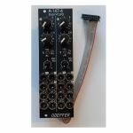
People also bought...
Doepfer A-147-4v Dual VCLFO Dual Voltage Controlled Low Frequency Oscillator Vintage Edition Module (black) (dual/stereo/LFO synth module)
Cat: 950730 Rel: 19 Jun 23 • View all Synth modules
Dual voltage controlled LFO (Low Frequency Oscillator) module - 8HP.
Notes: Module A-147-4V is a dual voltage controlled LFO (Low Frequency Oscillator). Each LFO has the five waveforms triangle, sine, rising and falling sawtooth, as well as rectangle available. The rectangle output features manually adjustable pulsewidth and pulsewidth modulation by means of an external control voltage. The core waveform is triangle. The other waveforms are derived from triangle by means of waveform converters. The frequency of each LFO can be adjusted manually and modulated by means of an external control voltage with associated attenuator and polarity switch. By means of a jumper the basic frequency range of each LFO can selected: about 0.02 Hz (~ 50 seconds) ... 2.5kHz or about 0.0017 Hz(~ 600 seconds) ... 220Hz. That way each LFO can be used also as a VCO with a max. frequency of about 2.5kHz. Each LFO features a reset input which can be used to reset the triangle signal.
The module has these controls and in/outputs available:
Control F : manual control of the frequency, for each LFO the frequency range can be selected by means of a jumper from two values (see technical notes)
frequency coverage of control F in the high frequency range: about 0.075 Hz (~ 13 seconds) ... 1,4kHz
frequency coverage of control F in the low frequency range: about 0.007 Hz (~ 140 seconds) ... 125Hz
Control CV: attenuator for the signal applied to the CV socket, by means of a jumper a small positive voltage can be applied to the switching contact of the /CV/ socket, as long as no patch cable is connected to /CV/ socket the CV control then works as fine control for the frequency
Switch CV Pol.: polarity switch for the signal applied to the socket /CV/
Control PW/PM: combined control for manual and CV control of the rectangle pulsewidth:
when no patch cable is connected to socket /P/ the control is used to adjust the pulsewidth (PW) manually
when a patch cable is connected to socket /P/ the control works as attenuator for the external CV signal with a basic pulsewidth of 50:50.
Socket /CV/: frequency control voltage input, in the factory the module is adjusted so that the sensitivity of this input is exactly 1V/octave when the CV control is fully CW.
Socket /R/: reset input, according to the associated jumper the reset input is edge triggered or level controlled (see technical notes for details)
Socket /P/: pulsewidth control voltage input
Sockets with waveform symbol: output of the waveform in question (triangle, sine, rising and falling sawtooth, rectangle)
The output voltage ranges are about -5V ... +5V (10Vpp), except the rectangle output
For the rectangle output one can choose by means of a jumper if the range is about -5V ... +5V or 0...+10V.
LED: visual control of the LFO (triangle)
The inputs of the module are labelled with white characters on black background (in the text included into two slashes). The outputs are labelled with black characters.
Technical notes and special features:
The basic frequency range of each LFO can be selected by means of a jumper. The settings correspond to two different capacitor values for the VCO circuit. The relation between the two ranges is about 1:11. When the upper range is selected frequencies from about 0.02 Hz up to 2.5kHz can be generated. For the lower range the values are about 0.0017 Hz ... 220Hz. To obtain these full frequency ranges external control voltages are required. With the frequency control F only the frequencies mentioned above are possible.
Apart from that the range for the manual control F can be reduced to obtain a finer resolution. For this a jumper has to be removed. The range of control F is then reduced to about 1:4.5 only.
In the factory the starting voltage of the triangle output after a reset is adjusted to 0V, i.e. the triangle starts from 0V with the rising slope after a reset. By means of a trimming potentiometer the starting voltage can be adjusted to another value (e.g. to -5V).
Another jumper is used to set the reset behaviour to edge triggered or level controlled. When set to edge triggered the rising edge of reset signal is used for the reset (independent of the duration of the "high" state of the reset signal). When set to level controlled the triangle output remains at the starting voltage as long as the reset signal is "high". Only when the reset signal turns "low" the triangle starts.
Power consumption: 80mA at +12 V and 70mA at -12 V
Depth: 45mm
HP : 8
… Read moreThe module has these controls and in/outputs available:
Control F : manual control of the frequency, for each LFO the frequency range can be selected by means of a jumper from two values (see technical notes)
frequency coverage of control F in the high frequency range: about 0.075 Hz (~ 13 seconds) ... 1,4kHz
frequency coverage of control F in the low frequency range: about 0.007 Hz (~ 140 seconds) ... 125Hz
Control CV: attenuator for the signal applied to the CV socket, by means of a jumper a small positive voltage can be applied to the switching contact of the /CV/ socket, as long as no patch cable is connected to /CV/ socket the CV control then works as fine control for the frequency
Switch CV Pol.: polarity switch for the signal applied to the socket /CV/
Control PW/PM: combined control for manual and CV control of the rectangle pulsewidth:
when no patch cable is connected to socket /P/ the control is used to adjust the pulsewidth (PW) manually
when a patch cable is connected to socket /P/ the control works as attenuator for the external CV signal with a basic pulsewidth of 50:50.
Socket /CV/: frequency control voltage input, in the factory the module is adjusted so that the sensitivity of this input is exactly 1V/octave when the CV control is fully CW.
Socket /R/: reset input, according to the associated jumper the reset input is edge triggered or level controlled (see technical notes for details)
Socket /P/: pulsewidth control voltage input
Sockets with waveform symbol: output of the waveform in question (triangle, sine, rising and falling sawtooth, rectangle)
The output voltage ranges are about -5V ... +5V (10Vpp), except the rectangle output
For the rectangle output one can choose by means of a jumper if the range is about -5V ... +5V or 0...+10V.
LED: visual control of the LFO (triangle)
The inputs of the module are labelled with white characters on black background (in the text included into two slashes). The outputs are labelled with black characters.
Technical notes and special features:
The basic frequency range of each LFO can be selected by means of a jumper. The settings correspond to two different capacitor values for the VCO circuit. The relation between the two ranges is about 1:11. When the upper range is selected frequencies from about 0.02 Hz up to 2.5kHz can be generated. For the lower range the values are about 0.0017 Hz ... 220Hz. To obtain these full frequency ranges external control voltages are required. With the frequency control F only the frequencies mentioned above are possible.
Apart from that the range for the manual control F can be reduced to obtain a finer resolution. For this a jumper has to be removed. The range of control F is then reduced to about 1:4.5 only.
In the factory the starting voltage of the triangle output after a reset is adjusted to 0V, i.e. the triangle starts from 0V with the rising slope after a reset. By means of a trimming potentiometer the starting voltage can be adjusted to another value (e.g. to -5V).
Another jumper is used to set the reset behaviour to edge triggered or level controlled. When set to edge triggered the rising edge of reset signal is used for the reset (independent of the duration of the "high" state of the reset signal). When set to level controlled the triangle output remains at the starting voltage as long as the reset signal is "high". Only when the reset signal turns "low" the triangle starts.
Power consumption: 80mA at +12 V and 70mA at -12 V
Depth: 45mm
HP : 8
1 in stock $170.21
Click for better price!
or call +44 20 7424 1960
quote 950730
quote 950730
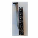
People also bought...
Doepfer A-101-8v Photo Phasing 8-Stage Phase Shifter Vintage Edition Module (black) (phase shifter/effect synth module)
Cat: 950741 Rel: 19 Jun 23 • View all Synth modules
8-stage phase shifter module - 4HP.
Notes: Module A-101-8V is a 8-stage phase shifter which uses light-sensitive resistors (LDR) and is a replica of the Compact Phasing A manufactured by the company Schulte in the seventies. The actual phasing circuit is identical to the historic model. Only the illumination control of the LDRs is different: the A-101-8 uses LEDs to illuminate the LDRs, the historic model used incandescent miniature lamps. And the A-101-8 has no built-in LFO but can be controlled by any external control voltage source (e.g. LFO, ADSR, random, Theremin, ribbon controller, sequencer, midi). The phasing offset (i.e. the base value for the phase shifting) and the modulation depth of the external control signal can be adjusted separately. The Compact Phasing A had no offset control but only a depth control for the built-in LFO. Feedback and mixing ratio of the output signal are set by two controls. The audio input is equipped with an attenuator. The module has two audio outputs available (same as the historic model) and a visual display of the phase shifting.
The module has these controls and in/outputs available:
Control Man. : manual control of the phase shift offset (base value)
Control CV: attenuator for the signal applied to the CV socket
Control Feedb.: Feedback or Resonance (similar function as filter resonance/feedback/emphasis)
Control Mix: sets the mixing ratio between original and phase shift signal appearing at output 1
fully CCW: only the modified input signal appears at output 1 (see note below *)
center: a mixture between the modified input signal and the phase shift signal appears at output 1, that's the standard position for the classical phasing effect
fully CW: the pure phase shifted signal appears at output 1 (e.g. for vibrato effects)
Control Input Level: attenuator for signal applied to the In socket
Socket In: audio input
Socket CV: control voltage input
Socket Out 1: audio output 1 (mix signal)
Socket Out 2: audio output 2 (modified input signal)
LED: visual control of the phase shift
The module has some peculiarities (same as the historic model):
The input signal is processed at first by a pre-stage which outputs a "modified" input signal (*). This signal is not processed by the phase shift stages but is affected by the feedback setting. Only when feedback is set to zero this signal is identical to the input signal. Otherwise it contains feedback components.
This signal is output on socket Out 2.
When both output sockets Out 1 and Out 2 are used as stereo channels one obtains a spatial stereo sound effect.
The same signals is also used for the CCW position of the mix control. With mix control fully CCW the unmodified signal appears only if the feedback control is set to zero. Otherwise it contains feedback components.
The historic model had two audio inputs: one 5-pin DIN socket and a 1/4" jack socket. The DIN socket was intended for high-level line signals. When the 1/4" jack socket was used the amplification of the pre-stage increased by about 100. The 1/4" jack socket was intended for low level signals (e.g. electric guitars or microphones). For this feature the A-101-8 has an internal jumper that can be used to increase the amplification. As long as the module is used within the A-100 system usually the lower amplification is used to avoid distortion.
The 8 photo resistors and LEDs are assembled within an small lightproof box. In addition the pc boards are made of lightproof black material to avoid interfering light from other modules or the bus board.
Power consumption: 30mA at +12 V and 30mA at -12 V
Depth: 45mm
HP : 4
… Read moreThe module has these controls and in/outputs available:
Control Man. : manual control of the phase shift offset (base value)
Control CV: attenuator for the signal applied to the CV socket
Control Feedb.: Feedback or Resonance (similar function as filter resonance/feedback/emphasis)
Control Mix: sets the mixing ratio between original and phase shift signal appearing at output 1
fully CCW: only the modified input signal appears at output 1 (see note below *)
center: a mixture between the modified input signal and the phase shift signal appears at output 1, that's the standard position for the classical phasing effect
fully CW: the pure phase shifted signal appears at output 1 (e.g. for vibrato effects)
Control Input Level: attenuator for signal applied to the In socket
Socket In: audio input
Socket CV: control voltage input
Socket Out 1: audio output 1 (mix signal)
Socket Out 2: audio output 2 (modified input signal)
LED: visual control of the phase shift
The module has some peculiarities (same as the historic model):
The input signal is processed at first by a pre-stage which outputs a "modified" input signal (*). This signal is not processed by the phase shift stages but is affected by the feedback setting. Only when feedback is set to zero this signal is identical to the input signal. Otherwise it contains feedback components.
This signal is output on socket Out 2.
When both output sockets Out 1 and Out 2 are used as stereo channels one obtains a spatial stereo sound effect.
The same signals is also used for the CCW position of the mix control. With mix control fully CCW the unmodified signal appears only if the feedback control is set to zero. Otherwise it contains feedback components.
The historic model had two audio inputs: one 5-pin DIN socket and a 1/4" jack socket. The DIN socket was intended for high-level line signals. When the 1/4" jack socket was used the amplification of the pre-stage increased by about 100. The 1/4" jack socket was intended for low level signals (e.g. electric guitars or microphones). For this feature the A-101-8 has an internal jumper that can be used to increase the amplification. As long as the module is used within the A-100 system usually the lower amplification is used to avoid distortion.
The 8 photo resistors and LEDs are assembled within an small lightproof box. In addition the pc boards are made of lightproof black material to avoid interfering light from other modules or the bus board.
Power consumption: 30mA at +12 V and 30mA at -12 V
Depth: 45mm
HP : 4
out of stock $143.22
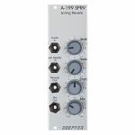
People also bought...
Doepfer A-199 SPRV Federhall Spring Reverb Module (silver) (effect/reverb synth module)
Cat: 577748 Rel: 15 Aug 18 • View all Synth modules
Reverb effects module with spring reverb tank - 8HP
Notes: Module A-199 is a spring reverb module. The reverb effect is electronically simulated by means of 3 spiral springs. Spring reverb systems have a very characteristic sound that is based on the (insufficient) mechanical properties of the springs like signal delays, audio resonances, limited frequency range, acoustic feedback behaviour, sensitivity to mechanical shocks and others.
The 3-spring system used in the A-199 ensures a "dense" reverb because of the different properties of the three springs.
The A-199 implies some special features that are not self-evident for spring reverb units:
The reverb signal can be fed back to the input using the Feedback control. Even self-oscillation of the springs similar to the self-oscillation of filters is available. The feedback loop can lead even via external modules like VCA, VCF, phaser, frequency shifter, vocoder, distortion/waveshaper, ring modulator and others. In this case the reverb output of the A-199 is connected to the input of the external module(s) and the output of the external module(s) is fed back to the Ext. Feedback In socket of the A-199. This socket contains a switch that interrupts the internal feedback loop as soon as a plug is inserted.
Another feature is the Emphasis control. This enables the adjustment of the accentuation of middle frequencies (around ~ 2kHz).
With the Mix control the relation between original and reverb signal appearing at the mix output is adjusted.
Using all these features very extreme and unusual effects can be generated with the A-199.
… Read moreThe 3-spring system used in the A-199 ensures a "dense" reverb because of the different properties of the three springs.
The A-199 implies some special features that are not self-evident for spring reverb units:
The reverb signal can be fed back to the input using the Feedback control. Even self-oscillation of the springs similar to the self-oscillation of filters is available. The feedback loop can lead even via external modules like VCA, VCF, phaser, frequency shifter, vocoder, distortion/waveshaper, ring modulator and others. In this case the reverb output of the A-199 is connected to the input of the external module(s) and the output of the external module(s) is fed back to the Ext. Feedback In socket of the A-199. This socket contains a switch that interrupts the internal feedback loop as soon as a plug is inserted.
Another feature is the Emphasis control. This enables the adjustment of the accentuation of middle frequencies (around ~ 2kHz).
With the Mix control the relation between original and reverb signal appearing at the mix output is adjusted.
Using all these features very extreme and unusual effects can be generated with the A-199.
1 in stock $106.48
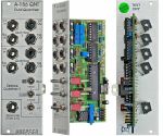
People also bought...
Doepfer A156 Dual Quantizer Module (silver) (B-STOCK) (dual/stereo/quantizer synth module)
Cat: 944515 Rel: 10 Sep 19 • View all Synth modules
B-STOCK: Item refurbished, repaired and in perfect working order.
Notes: ***B-STOCK: Item refurbished, repaired and in perfect working order.***
Module A-156 is a Dual Control Voltage Quantizer. A quantizer converts a continuous control voltage in the range 0...+10V into a stepped output voltage in the same voltage range (i.e. only certain voltages occur). Normally 1/12 V steps are used to obtain semitone steps. Quantizer 2 of the A-156 allows has more sophisticated quantizing modes like major scale (i.e. only voltages corresponding to the major scale), minor scale, major chord, minor chord, fundamental + fifth and addition of seventh or sixth when chords are selected. Only those voltages appear at the CV output which comply with the selection rule (e.g. minor chord with seventh). The mode setting of quantizer 2 is done with 3 switches (1-0-1 type with middle position). From the factory quantizer 1 is working in the semitone mode. But there is a jumper on the pc board that can be changed so that even quantizer 1 uses the same scale as quantizer 2.
For each quantizer the following in/outputs are available:
- Control voltage input (CV In): The input for the continuous voltage to be quantized
- Control voltage output (CV Out): The output of the quantized voltage
- Trigger input (Trig.In): If this jack is left open the quantizer is working permanently. If a rectangle voltage is applied quantisation happens only at the rising edge of the signal (e.g. from an LFO or MIDI-to-Sync interface). Thus the quantizing can be synchronized with other events
- Trigger output (Trig.Out): Whenever a quantisation happens (i.e. a new voltage is generated at the CV Out) a positive pulse occurs at this output. It may be used to trigger an envelope generator (ADSR) or for triggering other modules (sequential switch A-151, trigger divider/sequencer A-160/161, trigger delay A-162, ...). If none of these functions are used the jack is left open
On top of that the A-156 is provided with a common transpose CV input having an additive effect on both quantizers. This input is quantized in semitone steps. A typical application is the transposition of a sequence generated by the A-155 by a second control voltage (e.g. coming from the MIDI-CV interface A-190).
Typical applications:
- Quantizing the CV sequence generated by an A-155 (semitone, only major scale, only minor scale and so on)
- Quantizing the voltage coming from the Trautonium Manual / Ribbon Controller A-198, Theremin A-178 or Light-to-CV module A-179 to get accurate semitones or major/minor scale tones
- Arpeggio-like effects with LFO, random, noise, envelope generators as CV sources (for negative or symmetrical voltages an offset must be added, e.g. with the offset/attenuator module A-129-3, to obtain positive voltages for the A-156 input)
… Read moreModule A-156 is a Dual Control Voltage Quantizer. A quantizer converts a continuous control voltage in the range 0...+10V into a stepped output voltage in the same voltage range (i.e. only certain voltages occur). Normally 1/12 V steps are used to obtain semitone steps. Quantizer 2 of the A-156 allows has more sophisticated quantizing modes like major scale (i.e. only voltages corresponding to the major scale), minor scale, major chord, minor chord, fundamental + fifth and addition of seventh or sixth when chords are selected. Only those voltages appear at the CV output which comply with the selection rule (e.g. minor chord with seventh). The mode setting of quantizer 2 is done with 3 switches (1-0-1 type with middle position). From the factory quantizer 1 is working in the semitone mode. But there is a jumper on the pc board that can be changed so that even quantizer 1 uses the same scale as quantizer 2.
For each quantizer the following in/outputs are available:
- Control voltage input (CV In): The input for the continuous voltage to be quantized
- Control voltage output (CV Out): The output of the quantized voltage
- Trigger input (Trig.In): If this jack is left open the quantizer is working permanently. If a rectangle voltage is applied quantisation happens only at the rising edge of the signal (e.g. from an LFO or MIDI-to-Sync interface). Thus the quantizing can be synchronized with other events
- Trigger output (Trig.Out): Whenever a quantisation happens (i.e. a new voltage is generated at the CV Out) a positive pulse occurs at this output. It may be used to trigger an envelope generator (ADSR) or for triggering other modules (sequential switch A-151, trigger divider/sequencer A-160/161, trigger delay A-162, ...). If none of these functions are used the jack is left open
On top of that the A-156 is provided with a common transpose CV input having an additive effect on both quantizers. This input is quantized in semitone steps. A typical application is the transposition of a sequence generated by the A-155 by a second control voltage (e.g. coming from the MIDI-CV interface A-190).
Typical applications:
- Quantizing the CV sequence generated by an A-155 (semitone, only major scale, only minor scale and so on)
- Quantizing the voltage coming from the Trautonium Manual / Ribbon Controller A-198, Theremin A-178 or Light-to-CV module A-179 to get accurate semitones or major/minor scale tones
- Arpeggio-like effects with LFO, random, noise, envelope generators as CV sources (for negative or symmetrical voltages an offset must be added, e.g. with the offset/attenuator module A-129-3, to obtain positive voltages for the A-156 input)
out of stock $104.10

People also bought...
Doepfer A-133 POL Dual Voltage Controlled Polarizer Module (dual/stereo/polarizer/VCA/ring modulator module)
Cat: 710951 Rel: 29 Nov 18 • View all Synth modules
Dual voltage controlled polariser module - 8HP
Notes: A-133 is a special dual voltage controlled amplifier that enables both positive and negative amplifications. Negative amplification means in this context that the signal is inverted. The main application of the module is the processing of control voltages, e.g. ADSR or LFO but the module can be used also for audio applications.
The amplification range is about -2.5....0....+2.5 (other amplification ranges for small additional charges, e.g. -1...+1 or -5...+5). Amplification can be adjusted manually (Man control) and by an external control voltage with attenuator (CV). The present amplification is displayed with two LEDs: one for positive and one for negative amplifications (not a signal display but amplification diplay, similar to A-134).
The overall amplification of the A-133 is defined by the resistors R18 (upper unit) and R32 (lower unit). The factory value is 270k for both. Lowering the value of the resistor reduces the amplification of the unit in question, increasing the value of the resistor increase the amplification of the unit in question. For example 100k (exact value 108k) reduces the amplification range to about -1 ... +1 (instead of -2.5 ... +2.5), 560k (exact value 2*270k = 540) increases the amplification range to about -5 ... +5.
Dimensions
8 HP
50 mm deep
Current draw
30 mA +12V
20 mA -12V
… Read moreThe amplification range is about -2.5....0....+2.5 (other amplification ranges for small additional charges, e.g. -1...+1 or -5...+5). Amplification can be adjusted manually (Man control) and by an external control voltage with attenuator (CV). The present amplification is displayed with two LEDs: one for positive and one for negative amplifications (not a signal display but amplification diplay, similar to A-134).
The overall amplification of the A-133 is defined by the resistors R18 (upper unit) and R32 (lower unit). The factory value is 270k for both. Lowering the value of the resistor reduces the amplification of the unit in question, increasing the value of the resistor increase the amplification of the unit in question. For example 100k (exact value 108k) reduces the amplification range to about -1 ... +1 (instead of -2.5 ... +2.5), 560k (exact value 2*270k = 540) increases the amplification range to about -5 ... +5.
Dimensions
8 HP
50 mm deep
Current draw
30 mA +12V
20 mA -12V
out of stock $55.62

People also bought...
Doepfer A-111-6v Miniature Synthesiser Voice Vintage Edition Module (black) (B-STOCK) (synth voice synth module)
Cat: 970408 Rel: 01 Jan 90 • View all Synth modules
B-STOCK: Slight dent om the edge, otherwise in perfect condition
Notes: ***B-STOCK: Slight dent om the edge, otherwise in perfect condition***
VCO:
- Tune: manual tune control (with an internal jumper the range can be set to ~ +/-1 half an octave or ~ +/-2.5 octaves)
- Oct: range switch -1 / 0 / +1 octave
- Mod: modulation depth (attenuator wired to the Mod. socket)
- Dest: switch that is used to address the modulation to frequency modulation (position FM) or pulsewidth modulation (positon PM), in centre positon no modulation
- PW: manual pulsewidth control for rectangle waveform, PW can be also modulated by the Mod. input as mentioned above
- Wave: waveform switch (sawtooth / off / triangle), the sum of the waveform chosen by this switch and the rectangle is fed into the VCF (to turn the rectangle off the PW control has to be set fully CCW or fully CW)
- 1V/Oct. (socket): external CV input for VCO frequency (1V/octave)
- Access to internal bus CV (via jumper, optional, please remove the bus jumper if this feature is not used to avoid unwanted frequency modulation as then the unused CV line of the bus works as a kind of antenna)
- Triangle core VCO, frequency range about 32Hz ... 8kHz
Balance unit:
- The balance unit is made of two VCAs which are controlled by the sum of manual Balance control and the balance CV input in the opposite direction.
- The audio input of VCA1 is hard-wired to the VCO output, audio input 2 is connected to the socket Ext.In.
- The output of the balance unit is used as audio input for the VCF
- Bal.: manual balance control, fully CCW the internal VCO is used, fully CW the external signal (Ext.In) is used, at centre position both signals have about the same level
- CV Bal.: CV input for balance (range about 0...+5V)
- Ext. In: external audio input for VCA2, about 5 Vpp level required for similar loudness as the internal VCO
- This socket is normalled to the internal VCO suboctave f/2 signal (rectangle with half the frequency), if no external signal is applied the suboctave signal is used as the second signal for the balance unit
VCF:
- 24 dB low pass
- Frq: manual frequency control
- FM1: frequency modulation depth (attenuator wired to the VCF FM1 socket, the socket is normalled to the internal Envelope signal and then FM1 controls the modulation depth of the internal envelope applied to the filter)
- FM2 (socket) : second CV input for VCF without attenuator (about 1V/octave), can be used e.g. for VCF tracking by connecting the same CV which is used also for the VCO frequency
- Res: manual resonance control (up to self oscillation)
- If the VCO is turned off (waveform switch = centre position, pulsewidth control = fully CCW or CW) and the VCF resonance is set to maximum the module can be used as a sine oscillator, the tracking at socket VCF FM2 is about 1V/octave (not as precise as the VCO but much better than most other filters)
- ~ 11 octaves frequency range (~ 10 Hz ... 20kHz)
VCA:
- Gain: manual amplitude control (initial gain), can be used to open the VCA without envelope signal
- VCA (switch): used to switch between gate and envelope as control signal for the VCA, in centre position the VCA is not controlled by envelope or gate
- Note: when gate is used the VCA is controlled directly by the gate signal (i.e. hard on/off), this may lead to clicking noise under certain conditions (especially with low VCO/VCF frequencies)
- Special control scale: exponential scale in the range from about -20dB to -80/90dB, linear scale from about -20dB to 0dB
- Remark: this special control scale results in a loudness behaviour that is a bit different from pure linear or exponential VCAs
- Out: audio output of the module (= VCA output)
Envelope:
- Gate (socket): Gate input (min. +5V), can be normalled to the bus gate signal by means of a jumper
- Att: manual control for Attack
- D/R: manual control for Decay/Release
- Env. (switch): used to switch between A/D, ADSR and A/R mode of the envelope generator, in centre position (ADSR) the sustain level is fixed to about 50%
- Envelope (socket): envelope output (about +10V)
- CVT (socket): CV input for time control, by means of two internal jumpers one can select which time parameters are controlled by the CVT input (e.g. A only or D/R only or A/D/R) and in which direction (i.e. if an increasing CVT shortens or stretches the time parameter in question)
- Envelope LED display
- Attack time range: ~ 1ms ... 5 sec (can be extended by using the CVT input)
- Decay/Release time range: ~ 1ms ... 15 sec (can be extended by using the CVT input)
… Read moreVCO:
- Tune: manual tune control (with an internal jumper the range can be set to ~ +/-1 half an octave or ~ +/-2.5 octaves)
- Oct: range switch -1 / 0 / +1 octave
- Mod: modulation depth (attenuator wired to the Mod. socket)
- Dest: switch that is used to address the modulation to frequency modulation (position FM) or pulsewidth modulation (positon PM), in centre positon no modulation
- PW: manual pulsewidth control for rectangle waveform, PW can be also modulated by the Mod. input as mentioned above
- Wave: waveform switch (sawtooth / off / triangle), the sum of the waveform chosen by this switch and the rectangle is fed into the VCF (to turn the rectangle off the PW control has to be set fully CCW or fully CW)
- 1V/Oct. (socket): external CV input for VCO frequency (1V/octave)
- Access to internal bus CV (via jumper, optional, please remove the bus jumper if this feature is not used to avoid unwanted frequency modulation as then the unused CV line of the bus works as a kind of antenna)
- Triangle core VCO, frequency range about 32Hz ... 8kHz
Balance unit:
- The balance unit is made of two VCAs which are controlled by the sum of manual Balance control and the balance CV input in the opposite direction.
- The audio input of VCA1 is hard-wired to the VCO output, audio input 2 is connected to the socket Ext.In.
- The output of the balance unit is used as audio input for the VCF
- Bal.: manual balance control, fully CCW the internal VCO is used, fully CW the external signal (Ext.In) is used, at centre position both signals have about the same level
- CV Bal.: CV input for balance (range about 0...+5V)
- Ext. In: external audio input for VCA2, about 5 Vpp level required for similar loudness as the internal VCO
- This socket is normalled to the internal VCO suboctave f/2 signal (rectangle with half the frequency), if no external signal is applied the suboctave signal is used as the second signal for the balance unit
VCF:
- 24 dB low pass
- Frq: manual frequency control
- FM1: frequency modulation depth (attenuator wired to the VCF FM1 socket, the socket is normalled to the internal Envelope signal and then FM1 controls the modulation depth of the internal envelope applied to the filter)
- FM2 (socket) : second CV input for VCF without attenuator (about 1V/octave), can be used e.g. for VCF tracking by connecting the same CV which is used also for the VCO frequency
- Res: manual resonance control (up to self oscillation)
- If the VCO is turned off (waveform switch = centre position, pulsewidth control = fully CCW or CW) and the VCF resonance is set to maximum the module can be used as a sine oscillator, the tracking at socket VCF FM2 is about 1V/octave (not as precise as the VCO but much better than most other filters)
- ~ 11 octaves frequency range (~ 10 Hz ... 20kHz)
VCA:
- Gain: manual amplitude control (initial gain), can be used to open the VCA without envelope signal
- VCA (switch): used to switch between gate and envelope as control signal for the VCA, in centre position the VCA is not controlled by envelope or gate
- Note: when gate is used the VCA is controlled directly by the gate signal (i.e. hard on/off), this may lead to clicking noise under certain conditions (especially with low VCO/VCF frequencies)
- Special control scale: exponential scale in the range from about -20dB to -80/90dB, linear scale from about -20dB to 0dB
- Remark: this special control scale results in a loudness behaviour that is a bit different from pure linear or exponential VCAs
- Out: audio output of the module (= VCA output)
Envelope:
- Gate (socket): Gate input (min. +5V), can be normalled to the bus gate signal by means of a jumper
- Att: manual control for Attack
- D/R: manual control for Decay/Release
- Env. (switch): used to switch between A/D, ADSR and A/R mode of the envelope generator, in centre position (ADSR) the sustain level is fixed to about 50%
- Envelope (socket): envelope output (about +10V)
- CVT (socket): CV input for time control, by means of two internal jumpers one can select which time parameters are controlled by the CVT input (e.g. A only or D/R only or A/D/R) and in which direction (i.e. if an increasing CVT shortens or stretches the time parameter in question)
- Envelope LED display
- Attack time range: ~ 1ms ... 5 sec (can be extended by using the CVT input)
- Decay/Release time range: ~ 1ms ... 15 sec (can be extended by using the CVT input)
1 in stock $165.03
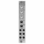
People also bought...
Doepfer A-105-2 24dB Low Pass (SSI-Type) Filter Module (silver) (filter/oscillator synth module)
Cat: 973741 Rel: 14 Nov 23 • View all Synth modules
24dB SSI low pass filter - 4HP.
Notes: Module A-105-2 is a voltage controlled low pass filter with 24dB/octave slope.
It is the successor of the A-105 which had to be discontinued because the obsolete SSM2044 filter circuit. The A-105-2 is based on the SSI2144 which is in turn the successor circuit of the SSM2044. The features of both modules are nearly the same. The main difference is the clearly reduced front panel width of the A-105-2 (4HP instead of 8HP) and the associated changes of the controls and sockets positions. In addition the A-105-2 is equipped with 2 audio inputs.
The module has these controls and in/outputs available:
Control Frequ: manual frequency control
Control FCV2: attenuator for the frequency control voltage applied to socket FCV2
Control Q: manual resonance control
Control QCV: attenuator for the resonance control voltage applied to socket QCV
Control Input 1 Level: attenuator for the audio input signal applied to socket Input 1
Socket Input 1: audio input 1 (with attenuator)
Socket Input 2: audio input 2 (without attenuator)
Socket FCV1: frequency control voltage 1 (without attenuator, about 1V/oct scale)
Socket FCV2: frequency control voltage 2 (with attenuator)
Socket QCV: resonance control voltage (with attenuator)
Socket Out: audio output
Technical notes:
Frequency range: about 15Hz ... 15 kHz
Resonance up to self oscillation
Max. input voltage at Input 2 without clipping/distortion: about 15Vpp
Max. output voltage without clipping/distortion: about 15Vpp
The signals of both inputs are mixed before they are processed by the filter. This saves an external mixer for small setups.
Depth: 45 mm
HP : 4
… Read moreIt is the successor of the A-105 which had to be discontinued because the obsolete SSM2044 filter circuit. The A-105-2 is based on the SSI2144 which is in turn the successor circuit of the SSM2044. The features of both modules are nearly the same. The main difference is the clearly reduced front panel width of the A-105-2 (4HP instead of 8HP) and the associated changes of the controls and sockets positions. In addition the A-105-2 is equipped with 2 audio inputs.
The module has these controls and in/outputs available:
Control Frequ: manual frequency control
Control FCV2: attenuator for the frequency control voltage applied to socket FCV2
Control Q: manual resonance control
Control QCV: attenuator for the resonance control voltage applied to socket QCV
Control Input 1 Level: attenuator for the audio input signal applied to socket Input 1
Socket Input 1: audio input 1 (with attenuator)
Socket Input 2: audio input 2 (without attenuator)
Socket FCV1: frequency control voltage 1 (without attenuator, about 1V/oct scale)
Socket FCV2: frequency control voltage 2 (with attenuator)
Socket QCV: resonance control voltage (with attenuator)
Socket Out: audio output
Technical notes:
Frequency range: about 15Hz ... 15 kHz
Resonance up to self oscillation
Max. input voltage at Input 2 without clipping/distortion: about 15Vpp
Max. output voltage without clipping/distortion: about 15Vpp
The signals of both inputs are mixed before they are processed by the filter. This saves an external mixer for small setups.
Depth: 45 mm
HP : 4
2 in stock $103.79
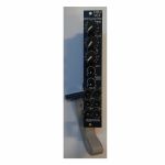
People also bought...
Doepfer A-105-2v 24dB Low Pass (SSI-Type) Filter Vintage Edition Module (black) (filter/oscillator synth module)
Cat: 973745 Rel: 14 Nov 23 • View all Synth modules
24dB SSI low pass filter module - 4HP.
Notes: Module A-105-2V is a voltage controlled low pass filter with 24dB/octave slope.
It is the successor of the A-105 which had to be discontinued because the obsolete SSM2044 filter circuit. The A-105-2 is based on the SSI2144 which is in turn the successor circuit of the SSM2044. The features of both modules are nearly the same. The main difference is the clearly reduced front panel width of the A-105-2 (4HP instead of 8HP) and the associated changes of the controls and sockets positions. In addition the A-105-2 is equipped with 2 audio inputs.
The module has these controls and in/outputs available:
Control Frequ: manual frequency control
Control FCV2: attenuator for the frequency control voltage applied to socket FCV2
Control Q: manual resonance control
Control QCV: attenuator for the resonance control voltage applied to socket QCV
Control Input 1 Level: attenuator for the audio input signal applied to socket Input 1
Socket Input 1: audio input 1 (with attenuator)
Socket Input 2: audio input 2 (without attenuator)
Socket FCV1: frequency control voltage 1 (without attenuator, about 1V/oct scale)
Socket FCV2: frequency control voltage 2 (with attenuator)
Socket QCV: resonance control voltage (with attenuator)
Socket Out: audio output
Technical notes:
Frequency range: about 15Hz ... 15 kHz
Resonance up to self oscillation
Max. input voltage at Input 2 without clipping/distortion: about 15Vpp
Max. output voltage without clipping/distortion: about 15Vpp
The signals of both inputs are mixed before they are processed by the filter. This saves an external mixer for small setups.
Depth: 45 mm
HP : 4
… Read moreIt is the successor of the A-105 which had to be discontinued because the obsolete SSM2044 filter circuit. The A-105-2 is based on the SSI2144 which is in turn the successor circuit of the SSM2044. The features of both modules are nearly the same. The main difference is the clearly reduced front panel width of the A-105-2 (4HP instead of 8HP) and the associated changes of the controls and sockets positions. In addition the A-105-2 is equipped with 2 audio inputs.
The module has these controls and in/outputs available:
Control Frequ: manual frequency control
Control FCV2: attenuator for the frequency control voltage applied to socket FCV2
Control Q: manual resonance control
Control QCV: attenuator for the resonance control voltage applied to socket QCV
Control Input 1 Level: attenuator for the audio input signal applied to socket Input 1
Socket Input 1: audio input 1 (with attenuator)
Socket Input 2: audio input 2 (without attenuator)
Socket FCV1: frequency control voltage 1 (without attenuator, about 1V/oct scale)
Socket FCV2: frequency control voltage 2 (with attenuator)
Socket QCV: resonance control voltage (with attenuator)
Socket Out: audio output
Technical notes:
Frequency range: about 15Hz ... 15 kHz
Resonance up to self oscillation
Max. input voltage at Input 2 without clipping/distortion: about 15Vpp
Max. output voltage without clipping/distortion: about 15Vpp
The signals of both inputs are mixed before they are processed by the filter. This saves an external mixer for small setups.
Depth: 45 mm
HP : 4
1 in stock $112.08
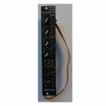
People also bought...
Doepfer A-130-2v VCAs Dual Linear/Exponential VCA Slim Line Series Vintage Edition Module (black) (dual/stereo/VCA synth module)
Cat: 973749 Rel: 14 Nov 23 • View all Synth modules
Dual linear/exponential VCA module - 4HP.
Notes: Module A-130-2v is composed of two identical voltage controlled amplifiers (VCA). Each VCA has a manual gain control (also named Initial Gain) and a control voltage input with attenuator. The character of the control scale can be switched to linear or exponential. All inputs and outputs are DC coupled. Consequently the VCAs can be used to process both audio and control voltages (e.g. for voltage control of the level of LFO or envelope signals). The signal input has no attenuator available but is capable to process up to 16Vpp signals (i.e. -8V...+8V) without distortion. For the processing of higher levels an external attenuator (e.g. A-183-1) is recommended.
The amplification range is 0...1. Even with a higher external control voltage the amplification remains at 1 (kind of "amplification clipping" at 1).
Controls (for each of both units):
Gain: manual gain control (Initial Gain) in the range 0...1
CV: attenuator for the CV input
lin/exp: switches the VCA characteristic to linear or exponential, in center position the VCA is off (mute function)
Inputs and outputs (for each of both units):
CV: control voltage input, min. +5V required for max. amplification (1) with CV control fully CW and Gain fully CCW
In: signal input, max. 16Vpp (+8V...-8V) without distortion
Out: signal output
A-130-2v is the slim version of module A-132-3 and offers essentially the same features. But the distances between the controls are smaller and rubberized small-sized knobs are used. In return the front panel has 4 HP only which is half the width of the A-132-3. The module is primarily planned for applications where only limited space is available.
Power consumption: 30mA at +12V and 30mA at -12V
Depth: 50mm
HP : 4
… Read moreThe amplification range is 0...1. Even with a higher external control voltage the amplification remains at 1 (kind of "amplification clipping" at 1).
Controls (for each of both units):
Gain: manual gain control (Initial Gain) in the range 0...1
CV: attenuator for the CV input
lin/exp: switches the VCA characteristic to linear or exponential, in center position the VCA is off (mute function)
Inputs and outputs (for each of both units):
CV: control voltage input, min. +5V required for max. amplification (1) with CV control fully CW and Gain fully CCW
In: signal input, max. 16Vpp (+8V...-8V) without distortion
Out: signal output
A-130-2v is the slim version of module A-132-3 and offers essentially the same features. But the distances between the controls are smaller and rubberized small-sized knobs are used. In return the front panel has 4 HP only which is half the width of the A-132-3. The module is primarily planned for applications where only limited space is available.
Power consumption: 30mA at +12V and 30mA at -12V
Depth: 50mm
HP : 4
2 in stock $94.45
Click for better price!
or call +44 20 7424 1960
quote 973749
quote 973749
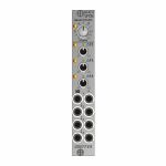
People also bought...
Doepfer A-147-5 Quad VCLFO Module (silver) (LFO synth module)
Cat: 973756 Rel: 14 Nov 23 • View all Synth modules
Quad VCLFO module - 4HP.
Notes: Module A-147-5 contains four voltage controlled low frequency oscillators (VCLFO) with triangle waveform outputs. All LFOs share a common frequency control. Each of the LFOs 2, 3 features a Delta control which is used to shift the frequency of the LFO in question up or down. With the Delta controls at center positions the frequencies of all LFOs are roughly the same. To control the frequencies by external control voltages four CV inputs are available which follow roughly the 1V/oct standard.
The module has these controls and in/outputs available:
Control F: manual control of the frequency for all four LFOs
Control Delta F2, F3 and F4: manual control of the frequency shift up/down for the LFO in question
Sockets CV 1...4: Frequency control voltage inputs (normalled from top to bottom)
Sockets with triangle symbol 1...4: triangle outputs
LEDs: visual displays of the triangle outputs (red = positive, yellow = negative output voltage)
Application examples:
Generation of four triangle modulation signals with a common frequency control for all LFOs and individual controls for the frequency deviation of each LFO, manually adjustable and controllable by external control voltages
Generation of modulation signals for polyphonic FM/PWM applications. For this the four CV inputs are connected to the same control voltages which are used to control the frequencies of the corresponding VCOs. That way each LFO follows the frequency of the associated VCO with the possibility to control the frequency of all VCOs (control F) and the frequency deviations (Delta F controls). For the simultaneous modulation depth control the Quad VCA module A-130-4 is recommended.
Generation of complex modulation signals by summing up the outputs (e.g. by means of a mixer module A-138n / A-138i / A-138j)
Technical notes:
The level of the triangle outputs is about +/-5V (10Vpp)
The manually adjustable frequency ranges from about 0.025 Hz (about 40 seconds) to about 50 Hz with the delta controls of LFOs 2, 3 and 4 about center position
The frequency deviations adjusted by the delta controls are about +/-1:5. Example: with 1 Hz in center position the frequency shift ranges from about 0.2 Hz in position -5 to about 5 Hz in position +5 (1 Hz/5 = 0.2 Hz, 1 Hz*5 = 5 Hz).
The manual frequency controls and the control voltage inputs have an exponential control behavior
With external control voltage the max. frequency is about 150 Hz, the minimum frequency
The scale of the CV inputs is roughly 1V/oct (not adjustable)
The CV inputs are normalled from top to bottom. Provided that only socket CV1 is patched CV1 controls the frequencies of all four LFOs.
When each CV input is patched to it's own control voltage each LFO is controlled individually by it's own CV. In this case CV1 controls only the frequency of LFO1.
Internally the rectangle outputs are available at four terminals (typ level +/-10V or 20Vpp). If required they can be wired to four sockets of a DIY breakout module made by the user, 1k protection resistors are recommended to avoid short circuits. If lower levels are required passive attenuators (voltage dividers) may be used.
Internally is even an (unbufferd) triangle sum signal available. For this each of the four triangle outputs is simply connected to the sum output terminal via a 47k resistor. This output has high impedance and should be buffered or amplified to avoid level drop when the load changes (e.g. by means of an A-180-3 or A-180-4 or A-183-3).
By changing the values of the capacitors in the LFO circuits even other frequency ranges are possible (e.g. Quad VCO to form kind of a cloud VCO). Pay attention that the accuracy of the CV input scales is not sufficient for precise 1V/oct VCO applications. The 1V/Oct scales cannot be adjusted and the circuits are not temperature compensated.
Dimensions
4 HP
45 mm deep
… Read moreThe module has these controls and in/outputs available:
Control F: manual control of the frequency for all four LFOs
Control Delta F2, F3 and F4: manual control of the frequency shift up/down for the LFO in question
Sockets CV 1...4: Frequency control voltage inputs (normalled from top to bottom)
Sockets with triangle symbol 1...4: triangle outputs
LEDs: visual displays of the triangle outputs (red = positive, yellow = negative output voltage)
Application examples:
Generation of four triangle modulation signals with a common frequency control for all LFOs and individual controls for the frequency deviation of each LFO, manually adjustable and controllable by external control voltages
Generation of modulation signals for polyphonic FM/PWM applications. For this the four CV inputs are connected to the same control voltages which are used to control the frequencies of the corresponding VCOs. That way each LFO follows the frequency of the associated VCO with the possibility to control the frequency of all VCOs (control F) and the frequency deviations (Delta F controls). For the simultaneous modulation depth control the Quad VCA module A-130-4 is recommended.
Generation of complex modulation signals by summing up the outputs (e.g. by means of a mixer module A-138n / A-138i / A-138j)
Technical notes:
The level of the triangle outputs is about +/-5V (10Vpp)
The manually adjustable frequency ranges from about 0.025 Hz (about 40 seconds) to about 50 Hz with the delta controls of LFOs 2, 3 and 4 about center position
The frequency deviations adjusted by the delta controls are about +/-1:5. Example: with 1 Hz in center position the frequency shift ranges from about 0.2 Hz in position -5 to about 5 Hz in position +5 (1 Hz/5 = 0.2 Hz, 1 Hz*5 = 5 Hz).
The manual frequency controls and the control voltage inputs have an exponential control behavior
With external control voltage the max. frequency is about 150 Hz, the minimum frequency
The scale of the CV inputs is roughly 1V/oct (not adjustable)
The CV inputs are normalled from top to bottom. Provided that only socket CV1 is patched CV1 controls the frequencies of all four LFOs.
When each CV input is patched to it's own control voltage each LFO is controlled individually by it's own CV. In this case CV1 controls only the frequency of LFO1.
Internally the rectangle outputs are available at four terminals (typ level +/-10V or 20Vpp). If required they can be wired to four sockets of a DIY breakout module made by the user, 1k protection resistors are recommended to avoid short circuits. If lower levels are required passive attenuators (voltage dividers) may be used.
Internally is even an (unbufferd) triangle sum signal available. For this each of the four triangle outputs is simply connected to the sum output terminal via a 47k resistor. This output has high impedance and should be buffered or amplified to avoid level drop when the load changes (e.g. by means of an A-180-3 or A-180-4 or A-183-3).
By changing the values of the capacitors in the LFO circuits even other frequency ranges are possible (e.g. Quad VCO to form kind of a cloud VCO). Pay attention that the accuracy of the CV input scales is not sufficient for precise 1V/oct VCO applications. The 1V/Oct scales cannot be adjusted and the circuits are not temperature compensated.
Dimensions
4 HP
45 mm deep
1 in stock $98.59
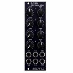
People also bought...
Doepfer A-138sv Mini Stereo Mixer Vintage Edition Module (black) (B-STOCK) (dual/stereo/mixer/panning/quad synth module)
Cat: 980376 Rel: 01 Jan 90 • View all Synth modules
B-STOCK: Item refurbished, repaired and in perfect working order.
Notes: ***B-STOCK: Item refurbished, repaired and in perfect working order.***
A-138s is a simple but useful 4-in-2 mixing tool. It has four inputs available. Each input is equipped with an attenuator (Level) and a panning control that is used to distribute the signal to the left and right output. Beyond stereo mixing it is equally suited to create variable parallel routings. For example: Any of the four inputs may be routed in variable intensity to feed two filters.
You may regard the A-138s as a smaller version of the A-138m Matrix Mixer.
Inputs and outputs are DC coupled, i.e. the module can be used for the mixing of control signals too.
- 3U Eurorack module, 8 HP wide, 30 mm in depth
- Power consumption: 10 mA at +12 V and 10 mA at -12 V
… Read moreA-138s is a simple but useful 4-in-2 mixing tool. It has four inputs available. Each input is equipped with an attenuator (Level) and a panning control that is used to distribute the signal to the left and right output. Beyond stereo mixing it is equally suited to create variable parallel routings. For example: Any of the four inputs may be routed in variable intensity to feed two filters.
You may regard the A-138s as a smaller version of the A-138m Matrix Mixer.
Inputs and outputs are DC coupled, i.e. the module can be used for the mixing of control signals too.
- 3U Eurorack module, 8 HP wide, 30 mm in depth
- Power consumption: 10 mA at +12 V and 10 mA at -12 V
1 in stock $77.71
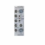
People also bought...
Doepfer A-196 PLL Phase Locked Loop Module (B-STOCK) (filter/oscillator/effect synth module)
Cat: 994989 Rel: 01 Jan 90 • View all Synth modules
B-STOCK: Box damaged, product in perfect working order
Notes: ***B-STOCK: Box damaged, product in perfect working order***
Module A-196 contains a so-called phase locked loop (PLL). The basic PLL system is shown in the sketch at the bottom of this page. A PLL consists of three parts: voltage-controlled oscillator (VCO), phase comparator (PC), and low-pass filter (LPF). All parts are normally connected to form a closed-loop frequency-feedback system.
This is how a PLL works: The output of the internal VCO (linear CV control, rectangle output) is compared with an external signal (e.g. the rectangle output of a A-110 VCO) in the so-called phase comparator (PC). The output of the phase comparator is a digital signal (low/high/tristate) that indicates if the frequency resp. phase difference of the two input signals is negative, zero or positive. The output of the phase comparator is processed by a low pass filter (LPF) to generate a smooth voltage that is used to control the frequency of the internal VCO. The 3 units VCO, PC and LPF form a feedback loop that works like this: The control voltage (output of the LPF) increases as long as the external frequency is higher than the frequency of the internal VCO und stops increasing when both frequencies become identical. The control voltage decreases as long as the external frequency is lower than the frequency of the internal VCO und stops decreasing when both frequencies become identical.
But there are some stumbling blocks: Different types of phase comparators with advantages and disadvantages can be made. Some phase comparators e.g. even lock at harmonics, i.e. if the two frequencies to be compared are integer multiples. But for some applications this can be used to create interesting effects. The A-196 contains 3 different types of phase comparators: PC1 is a simple exclusive OR, that even locks at harmonics. PC2 is a so-called RS flipflop and PC3 a more complex digital memory network. The user can select one of the three phase comparators with a 3-position switch. When PC2 is used a LED displays the "locked" state, i.e. when the frequency of the internal VCO is identical to the external frequency.
Special attention has to be directed to the frequency of the LPF. To obtain a smooth control voltage for the VCO the frequency of the LPF has to be much smaller than the lowest frequency of the internal or external audio signal. Otherwise the frequency of the internal VCO will jitter or wobble around the correct frequency. But for special effects this frequency jitter can be used intentionally. Example: frequencies in the range 50Hz...1kHz have to be processed with the PLL. Therefore the frequency of the LPF has to be about 10Hz or even less. Such a low frequency of the LPF causes a noticeable slew of the internal VCO. When the frequency of the external signal jumps e.g. between 500Hz and 1kHz it takes about 0.1 second until the internal VCO reaches the new frequency (like portamento). So one has to find a compromise between frequency jitter and portamento. But these remarks are valid only for the "ideal" working PLL. As the A-196 is used in a musical environment the "problems" and disadvantages with jitter and slew time lead to additional musical applications like portamento effects, wobbling frequencies or harmonic locking according to the type of frequency comparator and time constant of the PLL low pass filter. Instead of the internal manually controlled low pass filter the voltage controlled slew limiter A-171 can be used to obtain voltage control of this parameter. Normal audio filters (e.g. A-120, A-121) cannot be used for this job as the minimum frequency is to high (down to a few Hz or even less necessary) and the signal has to be DC coupled due to the low frequencies. Audio filters are normally AC coupled.
Another very important application of a PLL is frequency multiplication in combination with an external frequency divider. For this the output of the PLL-VCO is processed through an external frequency divider (e.g. A-163, A-160, A-161, A-115) before it is fed to In1 of the phase comparator. In this case the frequency of the PLL-VCO will be a multiple of the master frequency. E.g. if the A-163 is used and adjusted to dividing factor 5 the frequency of the PLL-VCO will be 5 times the frequency of the master VCO. Consequently, frequency division (A-163) leads to frequency multiplication with the PLL circuit. In combination with the PLL low pass frequency several effects can be realized (frequency multiplication with portamento or wobbling). The frequency multiplication can even be used to drive a graphic VCO. If your graphic VCO e.g. has 8 steps (e.g. A-155) and you use a frequency divider with factor 8 in the PLL feedback the output of the graphic VCO has the same frequency as the master VCO. Another application is the generation of pseudo-harmonics (not real harmonics as only rectangle waves are available) or clock generation for switched-capacitor filters.
… Read moreModule A-196 contains a so-called phase locked loop (PLL). The basic PLL system is shown in the sketch at the bottom of this page. A PLL consists of three parts: voltage-controlled oscillator (VCO), phase comparator (PC), and low-pass filter (LPF). All parts are normally connected to form a closed-loop frequency-feedback system.
This is how a PLL works: The output of the internal VCO (linear CV control, rectangle output) is compared with an external signal (e.g. the rectangle output of a A-110 VCO) in the so-called phase comparator (PC). The output of the phase comparator is a digital signal (low/high/tristate) that indicates if the frequency resp. phase difference of the two input signals is negative, zero or positive. The output of the phase comparator is processed by a low pass filter (LPF) to generate a smooth voltage that is used to control the frequency of the internal VCO. The 3 units VCO, PC and LPF form a feedback loop that works like this: The control voltage (output of the LPF) increases as long as the external frequency is higher than the frequency of the internal VCO und stops increasing when both frequencies become identical. The control voltage decreases as long as the external frequency is lower than the frequency of the internal VCO und stops decreasing when both frequencies become identical.
But there are some stumbling blocks: Different types of phase comparators with advantages and disadvantages can be made. Some phase comparators e.g. even lock at harmonics, i.e. if the two frequencies to be compared are integer multiples. But for some applications this can be used to create interesting effects. The A-196 contains 3 different types of phase comparators: PC1 is a simple exclusive OR, that even locks at harmonics. PC2 is a so-called RS flipflop and PC3 a more complex digital memory network. The user can select one of the three phase comparators with a 3-position switch. When PC2 is used a LED displays the "locked" state, i.e. when the frequency of the internal VCO is identical to the external frequency.
Special attention has to be directed to the frequency of the LPF. To obtain a smooth control voltage for the VCO the frequency of the LPF has to be much smaller than the lowest frequency of the internal or external audio signal. Otherwise the frequency of the internal VCO will jitter or wobble around the correct frequency. But for special effects this frequency jitter can be used intentionally. Example: frequencies in the range 50Hz...1kHz have to be processed with the PLL. Therefore the frequency of the LPF has to be about 10Hz or even less. Such a low frequency of the LPF causes a noticeable slew of the internal VCO. When the frequency of the external signal jumps e.g. between 500Hz and 1kHz it takes about 0.1 second until the internal VCO reaches the new frequency (like portamento). So one has to find a compromise between frequency jitter and portamento. But these remarks are valid only for the "ideal" working PLL. As the A-196 is used in a musical environment the "problems" and disadvantages with jitter and slew time lead to additional musical applications like portamento effects, wobbling frequencies or harmonic locking according to the type of frequency comparator and time constant of the PLL low pass filter. Instead of the internal manually controlled low pass filter the voltage controlled slew limiter A-171 can be used to obtain voltage control of this parameter. Normal audio filters (e.g. A-120, A-121) cannot be used for this job as the minimum frequency is to high (down to a few Hz or even less necessary) and the signal has to be DC coupled due to the low frequencies. Audio filters are normally AC coupled.
Another very important application of a PLL is frequency multiplication in combination with an external frequency divider. For this the output of the PLL-VCO is processed through an external frequency divider (e.g. A-163, A-160, A-161, A-115) before it is fed to In1 of the phase comparator. In this case the frequency of the PLL-VCO will be a multiple of the master frequency. E.g. if the A-163 is used and adjusted to dividing factor 5 the frequency of the PLL-VCO will be 5 times the frequency of the master VCO. Consequently, frequency division (A-163) leads to frequency multiplication with the PLL circuit. In combination with the PLL low pass frequency several effects can be realized (frequency multiplication with portamento or wobbling). The frequency multiplication can even be used to drive a graphic VCO. If your graphic VCO e.g. has 8 steps (e.g. A-155) and you use a frequency divider with factor 8 in the PLL feedback the output of the graphic VCO has the same frequency as the master VCO. Another application is the generation of pseudo-harmonics (not real harmonics as only rectangle waves are available) or clock generation for switched-capacitor filters.
out of stock $69.85
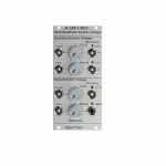
People also bought...
Doepfer A-149-1 RCV Quantized/Stored Random Voltages Module (B-STOCK) (modular synthesiser)
Cat: 1015712 Rel: 01 Jan 90 • View all Synth modules
B-STOCK: Box opened, product in perfect working order
Notes: ***B-STOCK: Box opened, product in perfect working order***
Module A-149-1 is the first module of the A-149-x range. In this group we present by popular request several functions of Don Buchla's "Source of Uncertainty 265/266" (SOU) modules that cannot be realized with existing A-100 modules. Many functions of Buchla's 265 and 266 SOU can be realized with existing A-100 modules. For details please refer to A-100 patch examples.
Module A-149-1 has available four different analogue random control voltages that are generated in different ways.
The "Quantized Random Voltages" section has available 2 CV outputs: "N+1 states" and "2N states". N is an integer number in the range 1...6 that can be adjusted with the manual control (Man N) and an external control voltage CVN with attenuator. Whenever the rising edge of the input clock signal (Clk In) appears a new random voltage is generated at the N+1 resp. 2N output. The N+1 output is capable to generate N+1 different voltage levels (or states), the 2N output up to 2N different states. If for example N is set to 4 the N+1 output generates up to 5, the 2N output 16 different states. The voltage steps of the 2N output are adjusted to 1/12 V in the factory. Consequently, exact semitones can be obtained in combination with a VCO. The voltage steps of the n+1 output are adjusted to 1.0 V in the factory corresponding to octave intervals in combination with a VCO. For each output a trimming potentiometer is available on the pc board that enables the user to select other voltage steps for the output in question.
Even the "Stored Random Voltages" section has 2 stepped CV outputs available: one with even voltage distribution of the max. 256 output states and second one with adjustable voltage distribution probability. The distribution probability is adjusted by a manual control (Man D) and an external control voltage CVD with attenuator. With the control set fully counter-clockwise most of the random voltages will be low magnitude but even medium and high magnitude voltages may appear but with smaller probability. As the control is turned to the right (or a positive control voltage appears at the CVD input) the distribution moves through medium to high magnitude voltage probability. The symbol at the lower jack socket shows this coherence graphically. The voltage range is 0...+5V for both outputs of the "Stored Random Voltages" section. For each output a trimming potentiometer is available on the pc board that enables the user to select another voltage range for the output in question.
The A-149-1 can be extended by 8 random digital voltages with the A-149-2 Digital Random Voltages module.
Dimensions
12 HP
60 mm deep
Current draw
40 mA +12V
10 mA -12V
… Read moreModule A-149-1 is the first module of the A-149-x range. In this group we present by popular request several functions of Don Buchla's "Source of Uncertainty 265/266" (SOU) modules that cannot be realized with existing A-100 modules. Many functions of Buchla's 265 and 266 SOU can be realized with existing A-100 modules. For details please refer to A-100 patch examples.
Module A-149-1 has available four different analogue random control voltages that are generated in different ways.
The "Quantized Random Voltages" section has available 2 CV outputs: "N+1 states" and "2N states". N is an integer number in the range 1...6 that can be adjusted with the manual control (Man N) and an external control voltage CVN with attenuator. Whenever the rising edge of the input clock signal (Clk In) appears a new random voltage is generated at the N+1 resp. 2N output. The N+1 output is capable to generate N+1 different voltage levels (or states), the 2N output up to 2N different states. If for example N is set to 4 the N+1 output generates up to 5, the 2N output 16 different states. The voltage steps of the 2N output are adjusted to 1/12 V in the factory. Consequently, exact semitones can be obtained in combination with a VCO. The voltage steps of the n+1 output are adjusted to 1.0 V in the factory corresponding to octave intervals in combination with a VCO. For each output a trimming potentiometer is available on the pc board that enables the user to select other voltage steps for the output in question.
Even the "Stored Random Voltages" section has 2 stepped CV outputs available: one with even voltage distribution of the max. 256 output states and second one with adjustable voltage distribution probability. The distribution probability is adjusted by a manual control (Man D) and an external control voltage CVD with attenuator. With the control set fully counter-clockwise most of the random voltages will be low magnitude but even medium and high magnitude voltages may appear but with smaller probability. As the control is turned to the right (or a positive control voltage appears at the CVD input) the distribution moves through medium to high magnitude voltage probability. The symbol at the lower jack socket shows this coherence graphically. The voltage range is 0...+5V for both outputs of the "Stored Random Voltages" section. For each output a trimming potentiometer is available on the pc board that enables the user to select another voltage range for the output in question.
The A-149-1 can be extended by 8 random digital voltages with the A-149-2 Digital Random Voltages module.
Dimensions
12 HP
60 mm deep
Current draw
40 mA +12V
10 mA -12V
1 in stock $99.63
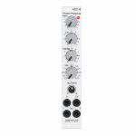
People also bought...
Doepfer A-101-8 Photo Phasing 8-Stage Phase Shifter Module (silver) (B-STOCK) (phase shifter/effect synth module)
Cat: 966281 Rel: 01 Jan 90 • View all Synth modules
B-STOCK: Box opened, but product is in excellent condition and in perfect working order
Notes: ***B-STOCK: Box opened, but product is in excellent condition and in perfect working order***
Module A-101-8 is a 8-stage phase shifter which uses light-sensitive resistors (LDR) and is a replica of the Compact Phasing A manufactured by the company Schulte in the seventies. The actual phasing circuit is identical to the historic model. Only the illumination control of the LDRs is different: the A-101-8 uses LEDs to illuminate the LDRs, the historic model used incandescent miniature lamps. And the A-101-8 has no built-in LFO but can be controlled by any external control voltage source (e.g. LFO, ADSR, random, Theremin, ribbon controller, sequencer, midi). The phasing offset (i.e. the base value for the phase shifting) and the modulation depth of the external control signal can be adjusted separately. The Compact Phasing A had no offset control but only a depth control for the built-in LFO. Feedback and mixing ratio of the output signal are set by two controls. The audio input is equipped with an attenuator. The module has two audio outputs available (same as the historic model) and a visual display of the phase shifting.
The module has these controls and in/outputs available:
Control Man. : manual control of the phase shift offset (base value)
Control CV: attenuator for the signal applied to the CV socket
Control Feedb.: Feedback or Resonance (similar function as filter resonance/feedback/emphasis)
Control Mix: sets the mixing ratio between original and phase shift signal appearing at output 1
fully CCW: only the modified input signal appears at output 1 (see note below *)
center: a mixture between the modified input signal and the phase shift signal appears at output 1, that's the standard position for the classical phasing effect
fully CW: the pure phase shifted signal appears at output 1 (e.g. for vibrato effects)
Control Input Level: attenuator for signal applied to the In socket
Socket In: audio input
Socket CV: control voltage input
Socket Out 1: audio output 1 (mix signal)
Socket Out 2: audio output 2 (modified input signal)
LED: visual control of the phase shift
The module has some peculiarities (same as the historic model):
The input signal is processed at first by a pre-stage which outputs a "modified" input signal (*). This signal is not processed by the phase shift stages but is affected by the feedback setting. Only when feedback is set to zero this signal is identical to the input signal. Otherwise it contains feedback components.
This signal is output on socket Out 2.
When both output sockets Out 1 and Out 2 are used as stereo channels one obtains a spatial stereo sound effect.
The same signals is also used for the CCW position of the mix control. With mix control fully CCW the unmodified signal appears only if the feedback control is set to zero. Otherwise it contains feedback components.
The historic model had two audio inputs: one 5-pin DIN socket and a 1/4" jack socket. The DIN socket was intended for high-level line signals. When the 1/4" jack socket was used the amplification of the pre-stage increased by about 100. The 1/4" jack socket was intended for low level signals (e.g. electric guitars or microphones). For this feature the A-101-8 has an internal jumper that can be used to increase the amplification. As long as the module is used within the A-100 system usually the lower amplification is used to avoid distortion.
The 8 photo resistors and LEDs are assembled within an small lighproof box. In addition the pc boards are made of lighproof black material to avoid interfering light from other modules or the bus board.
Dimensions
4 HP
45 mm deep
Current Draw
30 mA +12V
30 mA -12V
… Read moreModule A-101-8 is a 8-stage phase shifter which uses light-sensitive resistors (LDR) and is a replica of the Compact Phasing A manufactured by the company Schulte in the seventies. The actual phasing circuit is identical to the historic model. Only the illumination control of the LDRs is different: the A-101-8 uses LEDs to illuminate the LDRs, the historic model used incandescent miniature lamps. And the A-101-8 has no built-in LFO but can be controlled by any external control voltage source (e.g. LFO, ADSR, random, Theremin, ribbon controller, sequencer, midi). The phasing offset (i.e. the base value for the phase shifting) and the modulation depth of the external control signal can be adjusted separately. The Compact Phasing A had no offset control but only a depth control for the built-in LFO. Feedback and mixing ratio of the output signal are set by two controls. The audio input is equipped with an attenuator. The module has two audio outputs available (same as the historic model) and a visual display of the phase shifting.
The module has these controls and in/outputs available:
Control Man. : manual control of the phase shift offset (base value)
Control CV: attenuator for the signal applied to the CV socket
Control Feedb.: Feedback or Resonance (similar function as filter resonance/feedback/emphasis)
Control Mix: sets the mixing ratio between original and phase shift signal appearing at output 1
fully CCW: only the modified input signal appears at output 1 (see note below *)
center: a mixture between the modified input signal and the phase shift signal appears at output 1, that's the standard position for the classical phasing effect
fully CW: the pure phase shifted signal appears at output 1 (e.g. for vibrato effects)
Control Input Level: attenuator for signal applied to the In socket
Socket In: audio input
Socket CV: control voltage input
Socket Out 1: audio output 1 (mix signal)
Socket Out 2: audio output 2 (modified input signal)
LED: visual control of the phase shift
The module has some peculiarities (same as the historic model):
The input signal is processed at first by a pre-stage which outputs a "modified" input signal (*). This signal is not processed by the phase shift stages but is affected by the feedback setting. Only when feedback is set to zero this signal is identical to the input signal. Otherwise it contains feedback components.
This signal is output on socket Out 2.
When both output sockets Out 1 and Out 2 are used as stereo channels one obtains a spatial stereo sound effect.
The same signals is also used for the CCW position of the mix control. With mix control fully CCW the unmodified signal appears only if the feedback control is set to zero. Otherwise it contains feedback components.
The historic model had two audio inputs: one 5-pin DIN socket and a 1/4" jack socket. The DIN socket was intended for high-level line signals. When the 1/4" jack socket was used the amplification of the pre-stage increased by about 100. The 1/4" jack socket was intended for low level signals (e.g. electric guitars or microphones). For this feature the A-101-8 has an internal jumper that can be used to increase the amplification. As long as the module is used within the A-100 system usually the lower amplification is used to avoid distortion.
The 8 photo resistors and LEDs are assembled within an small lighproof box. In addition the pc boards are made of lighproof black material to avoid interfering light from other modules or the bus board.
Dimensions
4 HP
45 mm deep
Current Draw
30 mA +12V
30 mA -12V
out of stock $112.53
