100% Sicheres Einkaufen
Studio equipment
Our full range of studio equipment from all the leading equipment and software brands. Guaranteed fast delivery and low prices.
100% Sicheres Einkaufen
DJ equipment
Our full range of DJ equipment from all the leading equipment and software brands. Guaranteed fast delivery and low prices. Visit Juno DJ

Hilfe
BestellenProbleme beim BestellenHäufig gestellte FragenKontaktiere unsKontaktiere uns (Lieferanten)Über JunoJuno DailyNew This WeekDJ & Studio StoreTagsFeedbackDatenschutzregelungReturns & refundsAGBFinanceJuno Vinyl DistributionJuno Vinyl WholesaleJuno Marketing and PR departmentPromote your label / releases


Filter
Stock

Coming Soon
Equipment
Format
Brand
Featured
Price
Tags
People also bought...
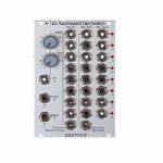
Doepfer A-152 Voltaged Addressed Track & Hold/Switch Module (switch/clock modulator/logic/sample & hold synth module)
Cat: 745781 Rel: 09 Sep 19 • View all Synth modules
Complex switch/multiplexer unit - 16HP
Notes: Module A152 is a very useful switching and T&H module. It combines a voltage addressed 1-to-8 multiplexer and 8 fold T&H that can be used as kind of an analogue shift register too. The active in/output is displayed by a LED. The digital output of the currently addressed step outputs "high". The remaining digital outputs are low.
Instead of voltage control even clock/reset controlled addressing of the active step is possible. The rising edge of each clock signal causes an advance to the next state. The rising edge of the reset signal resets to step 1.
The sum of the voltages coming from the manual Address control and the CV input define the currently addressed step of the 3 sub-devices. If the module is controlled by clock and reset the control voltage has to remain unchanged as the CV control has priority over the clock/reset control (e.g. simply turn the CV control fully counter-clockwise and do not touch the Address control knob).
Sub-device #1 is the bidirectional 8-fold multiplexer (kind of an electronical 8-fold rotary switch). Bidirectional means that it works into both directions like a mechanical rotary switch: the common socket may work as an output that is connected to one of the 8 inputs that are e.g. connected to modulation or audio sources. But the common socket may even function as input. In this case the signal applied to the common socket is output to the currently addressed single socket. The voltage range of the in/outputs to be switched is the full A-100 voltage range -12V....+12V. All A-100 signals can be switched without any restrictions.
Sub-device #2 is the addressed 8-fold T&H. The signal at the common T&H input is connected to the addressed T&H output. As soon as a new output is addressed the last voltage is stored at the output (Track&Hold function). The T&H section of the A-152 allows the emulation of the "toggling T&H" function of the Buchla module 266 "Source of Uncertainty". Only the first two T&H outputs of the A-152 are required for this application. This unit can be used also as kind of an analogue (shift) register. The difference to a "real" analogue shift register is that the sampled output voltages are not shifted to the next output but remain allocated to the same output. But in some cases (e.g. controlling the pitch of 3 VCOs by 3 output voltages of the A-152) the result is the same.
Sub-device #3 is the digital output section. The digital output of the currently addressed turns to "high". All other digital outputs are low. The digital outputs can be used to trigger e.g. envelope generators or to control the reset input in the clocked mode to reduce the number of addressed stages.
… Read moreInstead of voltage control even clock/reset controlled addressing of the active step is possible. The rising edge of each clock signal causes an advance to the next state. The rising edge of the reset signal resets to step 1.
The sum of the voltages coming from the manual Address control and the CV input define the currently addressed step of the 3 sub-devices. If the module is controlled by clock and reset the control voltage has to remain unchanged as the CV control has priority over the clock/reset control (e.g. simply turn the CV control fully counter-clockwise and do not touch the Address control knob).
Sub-device #1 is the bidirectional 8-fold multiplexer (kind of an electronical 8-fold rotary switch). Bidirectional means that it works into both directions like a mechanical rotary switch: the common socket may work as an output that is connected to one of the 8 inputs that are e.g. connected to modulation or audio sources. But the common socket may even function as input. In this case the signal applied to the common socket is output to the currently addressed single socket. The voltage range of the in/outputs to be switched is the full A-100 voltage range -12V....+12V. All A-100 signals can be switched without any restrictions.
Sub-device #2 is the addressed 8-fold T&H. The signal at the common T&H input is connected to the addressed T&H output. As soon as a new output is addressed the last voltage is stored at the output (Track&Hold function). The T&H section of the A-152 allows the emulation of the "toggling T&H" function of the Buchla module 266 "Source of Uncertainty". Only the first two T&H outputs of the A-152 are required for this application. This unit can be used also as kind of an analogue (shift) register. The difference to a "real" analogue shift register is that the sampled output voltages are not shifted to the next output but remain allocated to the same output. But in some cases (e.g. controlling the pitch of 3 VCOs by 3 output voltages of the A-152) the result is the same.
Sub-device #3 is the digital output section. The digital output of the currently addressed turns to "high". All other digital outputs are low. The digital outputs can be used to trigger e.g. envelope generators or to control the reset input in the clocked mode to reduce the number of addressed stages.
1 in stock $141.15
People also bought...
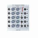
Doepfer A-154 Enhanced Sequencer Controller Module (silver) (sequencer/clock generator synth module)
Cat: 745782 Rel: 09 Sep 19 • View all Synth modules
Controller unit for the A-155 sequencer
Notes: Module A-154 is a supplement to the A-155 Analog/Trigger Sequencer module. It offers a lot of new features that are not available in the basic control unit of the A-155. The A-154 is used to replace the control unit of one or two A-155, i.e. the section marked "Control" with Start / Stop / Step / Reset buttons and inputs in the upper left corner of the A-155 front panel. If the A-154 is used to control the A-155 the control section of the A-155 is put out of action.
These are the features of the A-154:
Several running modes: forward, backward, pendulum, random, CV controlled step addressing. All modes are available as loop or one-shot.
LED display of the 5 different current modes and one LED for loop/one-shot display
Manual and voltage controlled selection (with attenuator) of the running mode. If no external control voltage is applied one of the 10 modes (5 modes x 2 loop/one-shot) is simply selected with a rotary knob. The CV input with attenuator is used to modulate the running mode with an external control voltage (digital high/low CV to switch between two modes or continuous analogue CV to sweep through different modes). With the combination of manual control and CV with attenuator it is possible e.g. to use only two neighbouring modes (e.g. forward/backward) or sweep through all possible running modes
Manual and voltage controlled selection (with attenuator) of first and last step of the sequence. The range is step 1...8 in 8 step mode resp. 1...16 in 16 step mode
If the running mode "CV Controlled Step Address" is selected the First Step section is used to determine the active sequencer step. Consequently manual and voltage controlled selection (with attenuator) of the active step is possible: the active step can be set by hand with the first step manual control and then modulated by an external control voltage (e.g. LFO, Random, S&H, Theremin, Light CV source, Joy Stick) at the first step CV input (with attenuator).
An internal voltage controlled clock generator with manual and CV control (with attenuator) is available. The output of the clock generator is displayed with a LED and is used as sequencer clock provided that no external clock signal is connected to the Clock In socket (normalled socket). If the CV input of the Clock section is connected to one of the analogue outputs of the sequencer the time for each step can be set separately. Even jumps (or skipping) will be possible as we will introduce the feature that a very short clock pulse will be generated if the control voltage exceeds a certain value. For example the gate row of the A-155 can be used to obtain skipping of steps: the gate output simply has to be connected to the CV input of the A-154 clock generator. If the corresponding switch of the A-155 is set correspondingly in the gate row the step will be skipped.
Manual and voltage controlled (with attenuator) pulse width (PW) of the clock signal. This features can be used to obtain a different gate length for each step: e.g. one of the CV outputs of the A-155 can be used to control the PW. With a PW control voltage coming from a LFO/random/S&H the gate length will change automatically. CV coming from Theremin A-178, ribbon controller A-198, light controlled CV A-179, joy stick A-174 are other ways to control the gate length.
8/16 step mode: A toggle switch us used to select 8 or 16 steps. The "16 step" mode requires two A-155 and one or more voltage controlled switches (e.g. A-150-1 or A-150-8). The voltage controlled switches are controlled by the "A3" output of the A-154. This output remains "low" as long as the active step is in the range 1...8 and turns to "high" in the range 9...16. The voltage controlled switches are used to switch between the CV/trigger/gates outputs of the first A-155 (step 1...8) and the second A-155 (step 9...16). In the A-154 user's manual the corresponding patch is shown.
If two A-155 are used they can work in parallel (8 steps) or serial (16 steps). The 8/16 steps switch determines if the 8 step mode (one A-155 or two A-155 in parallel) or the 16 step mode (two A-155 serial) is chosen. Both modes work with CV controlled step addressing too (see below). In 8 step mode only the steps 1...8 are addressed, in 16 step mode the steps 1...16. For serial operation an additional VC switch (A-150) is required - as mentioned above.
… Read moreThese are the features of the A-154:
Several running modes: forward, backward, pendulum, random, CV controlled step addressing. All modes are available as loop or one-shot.
LED display of the 5 different current modes and one LED for loop/one-shot display
Manual and voltage controlled selection (with attenuator) of the running mode. If no external control voltage is applied one of the 10 modes (5 modes x 2 loop/one-shot) is simply selected with a rotary knob. The CV input with attenuator is used to modulate the running mode with an external control voltage (digital high/low CV to switch between two modes or continuous analogue CV to sweep through different modes). With the combination of manual control and CV with attenuator it is possible e.g. to use only two neighbouring modes (e.g. forward/backward) or sweep through all possible running modes
Manual and voltage controlled selection (with attenuator) of first and last step of the sequence. The range is step 1...8 in 8 step mode resp. 1...16 in 16 step mode
If the running mode "CV Controlled Step Address" is selected the First Step section is used to determine the active sequencer step. Consequently manual and voltage controlled selection (with attenuator) of the active step is possible: the active step can be set by hand with the first step manual control and then modulated by an external control voltage (e.g. LFO, Random, S&H, Theremin, Light CV source, Joy Stick) at the first step CV input (with attenuator).
An internal voltage controlled clock generator with manual and CV control (with attenuator) is available. The output of the clock generator is displayed with a LED and is used as sequencer clock provided that no external clock signal is connected to the Clock In socket (normalled socket). If the CV input of the Clock section is connected to one of the analogue outputs of the sequencer the time for each step can be set separately. Even jumps (or skipping) will be possible as we will introduce the feature that a very short clock pulse will be generated if the control voltage exceeds a certain value. For example the gate row of the A-155 can be used to obtain skipping of steps: the gate output simply has to be connected to the CV input of the A-154 clock generator. If the corresponding switch of the A-155 is set correspondingly in the gate row the step will be skipped.
Manual and voltage controlled (with attenuator) pulse width (PW) of the clock signal. This features can be used to obtain a different gate length for each step: e.g. one of the CV outputs of the A-155 can be used to control the PW. With a PW control voltage coming from a LFO/random/S&H the gate length will change automatically. CV coming from Theremin A-178, ribbon controller A-198, light controlled CV A-179, joy stick A-174 are other ways to control the gate length.
8/16 step mode: A toggle switch us used to select 8 or 16 steps. The "16 step" mode requires two A-155 and one or more voltage controlled switches (e.g. A-150-1 or A-150-8). The voltage controlled switches are controlled by the "A3" output of the A-154. This output remains "low" as long as the active step is in the range 1...8 and turns to "high" in the range 9...16. The voltage controlled switches are used to switch between the CV/trigger/gates outputs of the first A-155 (step 1...8) and the second A-155 (step 9...16). In the A-154 user's manual the corresponding patch is shown.
If two A-155 are used they can work in parallel (8 steps) or serial (16 steps). The 8/16 steps switch determines if the 8 step mode (one A-155 or two A-155 in parallel) or the 16 step mode (two A-155 serial) is chosen. Both modes work with CV controlled step addressing too (see below). In 8 step mode only the steps 1...8 are addressed, in 16 step mode the steps 1...16. For serial operation an additional VC switch (A-150) is required - as mentioned above.
out of stock $160.87
People also bought...
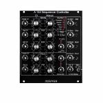
Doepfer A-154v Sequencer Controller Vintage Edition Module (black) (sequencer module)
Cat: 745783 Rel: 09 Sep 19 • View all Synth modules
Sequencer controller module - 22HP.
Notes: Module A-154 is a supplement to the A-155 Analog/Trigger Sequencer module. It offers a lot of new features that are not available in the basic control unit of the A-155. The A-154 is used to replace the control unit of one or two A-155, i.e. the section marked "Control" with Start / Stop / Step / Reset buttons and inputs in the upper left corner of the A-155 front panel. If the A-154 is used to control the A-155 the control section of the A-155 is put out of action.
These are the features of the A-154:
Several running modes: forward, backward, pendulum, random, CV controlled step adressing. All modes are available as loop or one-shot.
LED display of the 5 different current modes and one LED for loop/one-shot display
Manual and voltage controlled selection (with attenuator) of the running mode. If no external control voltage is applied one of the 10 modes (5 modes x 2 loop/one-shot) is simply selected with a rotary knob. The CV input with attenuator is used to modulate the running mode with an external control voltage (digital high/low CV to switch between two modes or continuous analog CV to sweep through different modes). With the combination of manual control and CV with attenuator it is possible e.g. to use only two neighbouring modes (e.g. forward/backward) or sweep through all possible running modes
Manual and voltage controlled selection (with attenuator) of first and last step of the sequence. The range is step 1...8 in 8 step mode resp. 1...16 in 16 step mode
If the running mode "CV Controlled Step Address" is selected the First Step section is used to determine the active sequencer step. Consequently manual and voltage controlled selection (with attenuator) of the active step is possible: the active step can be set by hand with the first step manual control and then modulated by an external control voltage (e.g. LFO, Random, S&H, Theremin, Light CV source, Joy Stick) at the first step CV input (with attenuator).
An internal voltage controlled clock generator with manual and CV control (with attenuator) is available. The output of the clock generator is displayed with a LED and is used as sequencer clock provided that no external clock signal is connected to the Clock In socket (normalled socket). If the CV input of the Clock section is connected to one of the analog outputs of the sequencer the time for each step can be set separately. Even jumps (or skipping) will be possible as we will introduce the feature that a very short clock pulse will be generated if the control voltage exceeds a certain value. For example the gate row of the A-155 can be used to obtain skipping of steps: the gate output simply has to be conneted to the CV input of the A-154 clock generator. If the corresponding switch of the A-155 is set correspondingly in the gate row the step will be skipped.
Manual and voltage controlled (with attenuator) pulse width (PW) of the clock signal. This features can be used to obtain a different gate length for each step: e.g. one of the CV outputs of the A-155 can be used to control the PW. With a PW control voltage coming from a LFO/random/S&H the gate length will change automatically. CV coming from Theremin A-178, ribbon controller A-198, light controlled CV A-179, joy stick A-174 are other ways to control the gate length.
8/16 step mode: A toggle switch us used to select 8 or 16 steps. The "16 step" mode requires two A-155 and one or more voltage controlled switches (e.g. A-150-1 or A-150-8). The voltage controlled switches are controlled by the "A3" output of the A-154. This output remains "low" as long as the active step is in the range 1...8 and turns to "high" in the range 9...16. The voltage controlled switches are used to switch between the CV/trigger/gates outputs of the first A-155 (step 1...8) and the second A-155 (step 9...16). In the A-154 user's manual the corresponding patch is shown.
If two A-155 are used they can work in parallel (8 steps) or serial (16 steps). The 8/16 steps switch determines if the 8 step mode (one A-155 or two A-155 in parallel) or the 16 step mode (two A-155 serial) is chosen. Both modes work with CV controlled step addressing too (see below). In 8 step mode only the steps 1...8 are addressed, in 16 step mode the steps 1...16. For serial operation an additional VC switch (A-150) is required - as mentioned above.
The functions of the Start/Stop/Step/Reset buttons and inputs are the same as for the "old" control unit of the A-155:
A high level at the Start input or operating the Start button starts the sequence from the momentarily addressed step. Not working in "CV controlled step address" mode.
A high level at the Stop input or operating the Stop button stops the sequence (the last active step remains addressed). Not working in "CV controlled step address" mode.
… Read moreThese are the features of the A-154:
Several running modes: forward, backward, pendulum, random, CV controlled step adressing. All modes are available as loop or one-shot.
LED display of the 5 different current modes and one LED for loop/one-shot display
Manual and voltage controlled selection (with attenuator) of the running mode. If no external control voltage is applied one of the 10 modes (5 modes x 2 loop/one-shot) is simply selected with a rotary knob. The CV input with attenuator is used to modulate the running mode with an external control voltage (digital high/low CV to switch between two modes or continuous analog CV to sweep through different modes). With the combination of manual control and CV with attenuator it is possible e.g. to use only two neighbouring modes (e.g. forward/backward) or sweep through all possible running modes
Manual and voltage controlled selection (with attenuator) of first and last step of the sequence. The range is step 1...8 in 8 step mode resp. 1...16 in 16 step mode
If the running mode "CV Controlled Step Address" is selected the First Step section is used to determine the active sequencer step. Consequently manual and voltage controlled selection (with attenuator) of the active step is possible: the active step can be set by hand with the first step manual control and then modulated by an external control voltage (e.g. LFO, Random, S&H, Theremin, Light CV source, Joy Stick) at the first step CV input (with attenuator).
An internal voltage controlled clock generator with manual and CV control (with attenuator) is available. The output of the clock generator is displayed with a LED and is used as sequencer clock provided that no external clock signal is connected to the Clock In socket (normalled socket). If the CV input of the Clock section is connected to one of the analog outputs of the sequencer the time for each step can be set separately. Even jumps (or skipping) will be possible as we will introduce the feature that a very short clock pulse will be generated if the control voltage exceeds a certain value. For example the gate row of the A-155 can be used to obtain skipping of steps: the gate output simply has to be conneted to the CV input of the A-154 clock generator. If the corresponding switch of the A-155 is set correspondingly in the gate row the step will be skipped.
Manual and voltage controlled (with attenuator) pulse width (PW) of the clock signal. This features can be used to obtain a different gate length for each step: e.g. one of the CV outputs of the A-155 can be used to control the PW. With a PW control voltage coming from a LFO/random/S&H the gate length will change automatically. CV coming from Theremin A-178, ribbon controller A-198, light controlled CV A-179, joy stick A-174 are other ways to control the gate length.
8/16 step mode: A toggle switch us used to select 8 or 16 steps. The "16 step" mode requires two A-155 and one or more voltage controlled switches (e.g. A-150-1 or A-150-8). The voltage controlled switches are controlled by the "A3" output of the A-154. This output remains "low" as long as the active step is in the range 1...8 and turns to "high" in the range 9...16. The voltage controlled switches are used to switch between the CV/trigger/gates outputs of the first A-155 (step 1...8) and the second A-155 (step 9...16). In the A-154 user's manual the corresponding patch is shown.
If two A-155 are used they can work in parallel (8 steps) or serial (16 steps). The 8/16 steps switch determines if the 8 step mode (one A-155 or two A-155 in parallel) or the 16 step mode (two A-155 serial) is chosen. Both modes work with CV controlled step addressing too (see below). In 8 step mode only the steps 1...8 are addressed, in 16 step mode the steps 1...16. For serial operation an additional VC switch (A-150) is required - as mentioned above.
The functions of the Start/Stop/Step/Reset buttons and inputs are the same as for the "old" control unit of the A-155:
A high level at the Start input or operating the Start button starts the sequence from the momentarily addressed step. Not working in "CV controlled step address" mode.
A high level at the Stop input or operating the Stop button stops the sequence (the last active step remains addressed). Not working in "CV controlled step address" mode.
out of stock $150.28
People also bought...
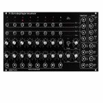
Doepfer A-155v Analogue Trigger Sequencer Vintage Edition Module (black) (sequencer module)
Cat: 745784 Rel: 09 Sep 19 • View all Synth modules
Analogue trigger sequencer module - 50HP.
Notes: The Doepfer A-155 has two CV rows, each with selectable voltage range, glide and sample & hold options. Three trigger rows and a one gate row. Logic inputs for clock, reset, start and stop. It's even possible to insert external signals per step instead, overriding the CV generated by the 2nd row's potentiometer. The A-155's functions can be expanded by the A-154 Sequencer Controller, as it's an entire control unit with step number limitation, voltage controllable clock generator, variable gate length and a number of playback modes.
Features of the analogue rows (knobs):
- 8 potentiometers (knobs)
- Lower row: Scale (knob), voltage output range 0 ... ~ +6,5V
- Upper row: 1V/2V/4V (octave range switch for exact VCO control), voltage output ranges 0 ...1.0V / 0 ...2.0V / 0 ...4.0V
- Glide time (knob), same as portamento or slew limiter
- Glide Control (control input for switching glide on/off)
- S&H Control (control input for internal S&H, works like A-148)
- Pre Glide/S&H-Out (analogue output before S&H and glide unit, especially required when external audio signals are used as inputs of the lower row)
- Post Glide/S&H-Out (analogue output after S&H and glide unit)
- Lower row: external inputs for the 8 steps (switched jack sockets), control signals or audio signals may be used as inputs (allowed voltage range -5V...+12V), the knobs of the lower row are working in this case as attenuators
Features of the trigger rows (switches):
- 4 Trigger/Gate tracks with 2 rows of switches
- Toggle switches of 1-0-1 type (with middle position), which can be used to send a trigger/gate to the track above or below or to send no trigger/gate (middle position)
- 3 trigger rows (i.e. short pulse for each step set, pulse width corresponds to the pulse width of the clock/step input signal)
- 1 gate row (i.e. a high signal is applied during the length of the step set)
Control inputs and buttons:
- Step (defines the tempo of the sequence, same as clock or trigger input)
- Reset (resets all rows to step 1)
- Start (starts the sequence at the momentary position)
- Stop (stops the sequence at the momentary position)
Step and Reset are compatible to the MIDI interface A-190, i.e. in combination with the A-190 the A-155 may be synchronized via MIDI. The quantizing module A-156 can be used to quantize the infinite analogue voltages coming from A-155 into discrete semitone steps (multiples of 1/12V). Without MIDI interface e.g. a LFO rectangle output can be used to define the tempo of the sequence.
The sequencer controller A-154 adds a lot of new functions to the A-155 (e.g. voltage controlled addressing, forward/backward/pendulum/random mode, voltage control of first and last step, voltage controlled clock and gate length, step skipping, combination of several A-155 in parallel/serial mode and many more).
… Read moreFeatures of the analogue rows (knobs):
- 8 potentiometers (knobs)
- Lower row: Scale (knob), voltage output range 0 ... ~ +6,5V
- Upper row: 1V/2V/4V (octave range switch for exact VCO control), voltage output ranges 0 ...1.0V / 0 ...2.0V / 0 ...4.0V
- Glide time (knob), same as portamento or slew limiter
- Glide Control (control input for switching glide on/off)
- S&H Control (control input for internal S&H, works like A-148)
- Pre Glide/S&H-Out (analogue output before S&H and glide unit, especially required when external audio signals are used as inputs of the lower row)
- Post Glide/S&H-Out (analogue output after S&H and glide unit)
- Lower row: external inputs for the 8 steps (switched jack sockets), control signals or audio signals may be used as inputs (allowed voltage range -5V...+12V), the knobs of the lower row are working in this case as attenuators
Features of the trigger rows (switches):
- 4 Trigger/Gate tracks with 2 rows of switches
- Toggle switches of 1-0-1 type (with middle position), which can be used to send a trigger/gate to the track above or below or to send no trigger/gate (middle position)
- 3 trigger rows (i.e. short pulse for each step set, pulse width corresponds to the pulse width of the clock/step input signal)
- 1 gate row (i.e. a high signal is applied during the length of the step set)
Control inputs and buttons:
- Step (defines the tempo of the sequence, same as clock or trigger input)
- Reset (resets all rows to step 1)
- Start (starts the sequence at the momentary position)
- Stop (stops the sequence at the momentary position)
Step and Reset are compatible to the MIDI interface A-190, i.e. in combination with the A-190 the A-155 may be synchronized via MIDI. The quantizing module A-156 can be used to quantize the infinite analogue voltages coming from A-155 into discrete semitone steps (multiples of 1/12V). Without MIDI interface e.g. a LFO rectangle output can be used to define the tempo of the sequence.
The sequencer controller A-154 adds a lot of new functions to the A-155 (e.g. voltage controlled addressing, forward/backward/pendulum/random mode, voltage control of first and last step, voltage controlled clock and gate length, step skipping, combination of several A-155 in parallel/serial mode and many more).
out of stock $247.43
People also bought...
Doepfer A-156v QNT Dual Quantizer Vintage Edition Module (black) (dual/stereo/quantizer synth module)
Cat: 745785 Rel: 10 Sep 19 • View all Synth modules
Dual quantizer for CV's, converting a continuous positive input voltage into a stepped output voltage - 8HP
Notes: Module A-156 is a Dual Control Voltage Quantizer. A quantizer converts a continuous control voltage in the range 0...+10V into a stepped output voltage in the same voltage range (i.e. only certain voltages occur). Normally 1/12 V steps are used to obtain semitone steps. Quantizer 2 of the A-156 allows has more sophisticated quantizing modes like major scale (i.e. only voltages corresponding to the major scale), minor scale, major chord, minor chord, fundamental + fifth and addition of seventh or sixth when chords are selected. Only those voltages appear at the CV output which comply with the selection rule (e.g. minor chord with seventh). The mode setting of quantizer 2 is done with 3 switches (1-0-1 type with middle position). From the factory quantizer 1 is working in the semitone mode. But there is a jumper on the pc board that can be changed so that even quantizer 1 uses the same scale as quantizer 2.
For each quantizer the following in/outputs are available:
- Control voltage input (CV In): The input for the continuous voltage to be quantized
- Control voltage output (CV Out): The output of the quantized voltage
- Trigger input (Trig.In): If this jack is left open the quantizer is working permanently. If a rectangle voltage is applied quantisation happens only at the rising edge of the signal (e.g. from an LFO or MIDI-to-Sync interface). Thus the quantizing can be synchronized with other events
- Trigger output (Trig.Out): Whenever a quantisation happens (i.e. a new voltage is generated at the CV Out) a positive pulse occurs at this output. It may be used to trigger an envelope generator (ADSR) or for triggering other modules (sequential switch A-151, trigger divider/sequencer A-160/161, trigger delay A-162, ...). If none of these functions are used the jack is left open
On top of that the A-156 is provided with a common transpose CV input having an additive effect on both quantizers. This input is quantized in semitone steps. A typical application is the transposition of a sequence generated by the A-155 by a second control voltage (e.g. coming from the MIDI-CV interface A-190).
Typical applications:
- Quantizing the CV sequence generated by an A-155 (semitone, only major scale, only minor scale and so on)
- Quantizing the voltage coming from the Trautonium Manual / Ribbon Controller A-198, Theremin A-178 or Light-to-CV module A-179 to get accurate semitones or major/minor scale tones
- Arpeggio-like effects with LFO, random, noise, envelope generators as CV sources (for negative or symmetrical voltages an offset must be added, e.g. with the offset/attenuator module A-129-3, to obtain positive voltages for the A-156 input)
… Read moreFor each quantizer the following in/outputs are available:
- Control voltage input (CV In): The input for the continuous voltage to be quantized
- Control voltage output (CV Out): The output of the quantized voltage
- Trigger input (Trig.In): If this jack is left open the quantizer is working permanently. If a rectangle voltage is applied quantisation happens only at the rising edge of the signal (e.g. from an LFO or MIDI-to-Sync interface). Thus the quantizing can be synchronized with other events
- Trigger output (Trig.Out): Whenever a quantisation happens (i.e. a new voltage is generated at the CV Out) a positive pulse occurs at this output. It may be used to trigger an envelope generator (ADSR) or for triggering other modules (sequential switch A-151, trigger divider/sequencer A-160/161, trigger delay A-162, ...). If none of these functions are used the jack is left open
On top of that the A-156 is provided with a common transpose CV input having an additive effect on both quantizers. This input is quantized in semitone steps. A typical application is the transposition of a sequence generated by the A-155 by a second control voltage (e.g. coming from the MIDI-CV interface A-190).
Typical applications:
- Quantizing the CV sequence generated by an A-155 (semitone, only major scale, only minor scale and so on)
- Quantizing the voltage coming from the Trautonium Manual / Ribbon Controller A-198, Theremin A-178 or Light-to-CV module A-179 to get accurate semitones or major/minor scale tones
- Arpeggio-like effects with LFO, random, noise, envelope generators as CV sources (for negative or symmetrical voltages an offset must be added, e.g. with the offset/attenuator module A-129-3, to obtain positive voltages for the A-156 input)
out of stock $126.62
People also bought...
Doepfer A-157-1/2 8x16 Trigger Sequencer Matrix Module Set 1/2/3 (drum/sequencer/expander module)
Cat: 745786 Rel: 09 Sep 19 • View all Synth modules
8-channel, 16-step-button step sequencer with breakout modules - 50HP
Notes: A-157 is a trigger sequencer subsystem that generates eight trigger signals controlled by a 8x16 LED/button matrix (some customers call it "Miniature Schaltwerk" as it is based on the same matrix as the no longer available Schaltwerk).
The subsystem contains three modules:
A-157-1: 8 x 16 LED/button matrix and function addressing buttons/LEDs
A-157-2: Trigger Output module
A-157-3: Control Inputs module
The LED/button matrix module A-157-1 is the core of the subsystem. It is used to set or reset the trigger event on each of the 16 steps of each of the 8 rows. In addition the buttons and LEDs of the matrix are used for other functions too (like setting the first and last step of each row or addressing the preset memory).
The Trigger Output module A-157-2 outputs the 8 trigger signals and has an LED display for each trigger available.
The Control Inputs module A-157-3 has manual controls and trigger inputs available for the basic control functions start, stop, reset and clock. In addition four functions inputs are available which will be used in future firmware versions to assign these inputs to special functions (e.g. shifting a row left or right by means of an external gate/trigger signal or a second set of start, stop, reset and clock for individual rows).
… Read moreThe subsystem contains three modules:
A-157-1: 8 x 16 LED/button matrix and function addressing buttons/LEDs
A-157-2: Trigger Output module
A-157-3: Control Inputs module
The LED/button matrix module A-157-1 is the core of the subsystem. It is used to set or reset the trigger event on each of the 16 steps of each of the 8 rows. In addition the buttons and LEDs of the matrix are used for other functions too (like setting the first and last step of each row or addressing the preset memory).
The Trigger Output module A-157-2 outputs the 8 trigger signals and has an LED display for each trigger available.
The Control Inputs module A-157-3 has manual controls and trigger inputs available for the basic control functions start, stop, reset and clock. In addition four functions inputs are available which will be used in future firmware versions to assign these inputs to special functions (e.g. shifting a row left or right by means of an external gate/trigger signal or a second set of start, stop, reset and clock for individual rows).
out of stock $429.69

People also bought...
Doepfer A-160-5 Voltage Controlled Clock Multiplier & Ratcheting Controller Module (silver) (clock modulator synth module)
Cat: 745787 Rel: 10 Sep 19 • View all Synth modules
Voltage-controlled clock multiplier with CV or manual control - 4HP
Notes: Module A-160-5 is a voltage controlled clock multiplier. The incoming clock signal (socket Clock In) is multiplied by a factor that depends upon the control voltage on socket CV In (0...+5V) and the position of the Mode switch. The multiplied clock signal is available at the socket Clock Out. According to the position of the Mode switch different clock multiplying factors are assigned to the control voltage. With 0V CV no clock output is generated. This state is indicated by "all LEDs off". With increasing CV integer factors (left position of the mode switch), power of two factors (middle position) or a mix of both (right position) are obtained. Nine LEDs are used to show the currently selected multiplying factor. In addition two LEDs are used to display the incoming and outgoing clock signal.
A manual control is used to adjust the clock multiplication factor manually without the need of an external control voltage. The voltage generated by this control ("Manual") is normalled to the CV In socket. As long as no plug is inserted into the CV In socket the clock multiplication factor is adjusted by means of the manual control knob and displayed by the LEDs. For dynamic applications (like the ratcheting function described below) the manually generated CV is overwritten by the external CV which has to be fed into the CV In socket.
The module can be used for all kind of clock multiplying applications. One important example is the generation of so-called ratcheting sequences. The band Tangerine Dream is famous for this kind of sequences. A normal sequencer generates only one gate signal per step. A ratcheting sequence may have also more than one gate pulses per step. This function can be obtained by using the A-160-5: one CV output of the sequencer is used to define the number of gate pulses per step. If the control of the step in question is fully CCW the generated CV is 0V and no gate signal is generated (mute of the step). When the control of the step in question is turned clockwise one, two or more gate pulses are generated depending upon the position of the mode switch and the voltage generated by the CV at this step.
Technical note: Due to the nature of clock multiplying it takes a few input clock pulses until the clock output is stable. One has to average a few input clock pulses to generate the multiplied clock output signal. Even when the input clock frequency changes it will take a few cycles until the output clock signal is correct as the module cannot foresee the future of the clock input signal. The generated clock output signal is derived from the last few cycles of the clock input signal. Consequently the module should be driven only by a clock signal with constant or slowly changing frequency.
… Read moreA manual control is used to adjust the clock multiplication factor manually without the need of an external control voltage. The voltage generated by this control ("Manual") is normalled to the CV In socket. As long as no plug is inserted into the CV In socket the clock multiplication factor is adjusted by means of the manual control knob and displayed by the LEDs. For dynamic applications (like the ratcheting function described below) the manually generated CV is overwritten by the external CV which has to be fed into the CV In socket.
The module can be used for all kind of clock multiplying applications. One important example is the generation of so-called ratcheting sequences. The band Tangerine Dream is famous for this kind of sequences. A normal sequencer generates only one gate signal per step. A ratcheting sequence may have also more than one gate pulses per step. This function can be obtained by using the A-160-5: one CV output of the sequencer is used to define the number of gate pulses per step. If the control of the step in question is fully CCW the generated CV is 0V and no gate signal is generated (mute of the step). When the control of the step in question is turned clockwise one, two or more gate pulses are generated depending upon the position of the mode switch and the voltage generated by the CV at this step.
Technical note: Due to the nature of clock multiplying it takes a few input clock pulses until the clock output is stable. One has to average a few input clock pulses to generate the multiplied clock output signal. Even when the input clock frequency changes it will take a few cycles until the output clock signal is correct as the module cannot foresee the future of the clock input signal. The generated clock output signal is derived from the last few cycles of the clock input signal. Consequently the module should be driven only by a clock signal with constant or slowly changing frequency.
out of stock $101.71
People also bought...
Doepfer A-160-5v Voltage Controlled Clock Multiplier & Ratcheting Controller Module (vintage edition) (synth module)
Cat: 745789 Rel: 10 Sep 19 • View all Synth modules
Voltage-controlled clock multiplier with CV or manual control - 4HP
Notes: Module A-160-5 is a voltage controlled clock multiplier. The incoming clock signal (socket Clock In) is multiplied by a factor that depends upon the control voltage on socket CV In (0...+5V) and the position of the Mode switch. The multiplied clock signal is available at the socket Clock Out. According to the position of the Mode switch different clock multiplying factors are assigned to the control voltage. With 0V CV no clock output is generated. This state is indicated by "all LEDs off". With increasing CV integer factors (left position of the mode switch), power of two factors (middle position) or a mix of both (right position) are obtained. Nine LEDs are used to show the currently selected multiplying factor. In addition two LEDs are used to display the incoming and outgoing clock signal.
A manual control is used to adjust the clock multiplication factor manually without the need of an external control voltage. The voltage generated by this control ("Manual") is normalled to the CV In socket. As long as no plug is inserted into the CV In socket the clock multiplication factor is adjusted by means of the manual control knob and displayed by the LEDs. For dynamic applications (like the ratcheting function described below) the manually generated CV is overwritten by the external CV which has to be fed into the CV In socket.
The module can be used for all kind of clock multiplying applications. One important example is the generation of so-called ratcheting sequences. The band Tangerine Dream is famous for this kind of sequences. A normal sequencer generates only one gate signal per step. A ratcheting sequence may have also more than one gate pulses per step. This function can be obtained by using the A-160-5: one CV output of the sequencer is used to define the number of gate pulses per step. If the control of the step in question is fully CCW the generated CV is 0V and no gate signal is generated (mute of the step). When the control of the step in question is turned clockwise one, two or more gate pulses are generated depending upon the position of the mode switch and the voltage generated by the CV at this step.
Technical note: Due to the nature of clock multiplying it takes a few input clock pulses until the clock output is stable. One has to average a few input clock pulses to generate the multiplied clock output signal. Even when the input clock frequency changes it will take a few cycles until the output clock signal is correct as the module cannot foresee the future of the clock input signal. The generated clock output signal is derived from the last few cycles of the clock input signal. Consequently the module should be driven only by a clock signal with constant or slowly changing frequency.
… Read moreA manual control is used to adjust the clock multiplication factor manually without the need of an external control voltage. The voltage generated by this control ("Manual") is normalled to the CV In socket. As long as no plug is inserted into the CV In socket the clock multiplication factor is adjusted by means of the manual control knob and displayed by the LEDs. For dynamic applications (like the ratcheting function described below) the manually generated CV is overwritten by the external CV which has to be fed into the CV In socket.
The module can be used for all kind of clock multiplying applications. One important example is the generation of so-called ratcheting sequences. The band Tangerine Dream is famous for this kind of sequences. A normal sequencer generates only one gate signal per step. A ratcheting sequence may have also more than one gate pulses per step. This function can be obtained by using the A-160-5: one CV output of the sequencer is used to define the number of gate pulses per step. If the control of the step in question is fully CCW the generated CV is 0V and no gate signal is generated (mute of the step). When the control of the step in question is turned clockwise one, two or more gate pulses are generated depending upon the position of the mode switch and the voltage generated by the CV at this step.
Technical note: Due to the nature of clock multiplying it takes a few input clock pulses until the clock output is stable. One has to average a few input clock pulses to generate the multiplied clock output signal. Even when the input clock frequency changes it will take a few cycles until the output clock signal is correct as the module cannot foresee the future of the clock input signal. The generated clock output signal is derived from the last few cycles of the clock input signal. Consequently the module should be driven only by a clock signal with constant or slowly changing frequency.
3 in stock $107.94
Click for better price!
or call +44 20 7424 1960
quote 745789
quote 745789

People also bought...
Doepfer A-162 TDEL Dual Trigger Delay Module (silver) (delay/dual/stereo/utility synth module)
Cat: 745790 Rel: 10 Sep 19 • View all Synth modules
8HP dual trigger delay for Eurorack
Notes: Module A-162 contains two identical circuits that generate a trigger signal with adjustable delay and length from an incoming rectangle signal (e.g. gate, trigger, rectangle output of an LFO or VCO). The rising edge of the incoming signal is used to trigger the new trigger signal. This module makes it possible to delay the onset of a trigger pulse, and also change its length.
On each of the two units, two controls can alter the onset time and duration of triggers, from about 2 ms up to more than 10 seconds. A control LED shows the generated signal.
… Read moreOn each of the two units, two controls can alter the onset time and duration of triggers, from about 2 ms up to more than 10 seconds. A control LED shows the generated signal.
out of stock $54.79

People also bought...
Doepfer A-163 Voltage Controlled Frequency Divider Module (synth module)
Cat: 745791 Rel: 10 Sep 19 • View all Synth modules
Simple & effective voltage-controlled frequency divider - 8HP
Notes: Module A-163 is a voltage controlled audio frequency divider. The frequency of the input signal (preferably the rectangle output of a VCO) is divided by an integer factor N (N = 1, 2, 3, 4 ... up to 32). N can be adjusted manually and modulated with an external control voltage (e.g. from LFO, ADSR, Random, MIDI-to-CV, Theremin, Light-to-CV, analogue sequencer) with attenuator. The control input has polarizing function, i.e. the manually adjusted dividing factor can be modulated upwards or downwards. The basic idea of a polarizer is described in the modules A-133 Voltage Controlled Polarizer and A-138c Polarizing Mixer.
The output waveform is rectangle with 50% duty cycle. Unlike the A-115 with fixed dividing factors (2, 4, 8, 16) the dividing factor of the A-163 is voltage controlled and can be any integer value between 1 and about 20 (but only one output). In contrast to A-113 the dividing factor of the A-163 is voltage controlled and the output waveform is rectangle (the A-113 has 4 sawtooth outputs with 4 adjustable but not voltage controlled dividers).
… Read moreThe output waveform is rectangle with 50% duty cycle. Unlike the A-115 with fixed dividing factors (2, 4, 8, 16) the dividing factor of the A-163 is voltage controlled and can be any integer value between 1 and about 20 (but only one output). In contrast to A-113 the dividing factor of the A-163 is voltage controlled and the output waveform is rectangle (the A-113 has 4 sawtooth outputs with 4 adjustable but not voltage controlled dividers).
out of stock $72.65

People also bought...
Cat: 745792 Rel: 10 Sep 19 • View all Synth modules
Dual trigger modifier, consisting of two trigger inverters for gate, clock or trigger signals - 4HP
Notes: Module A-165 (Dual Trigger Modifier) contains two separate trigger modifiers, to use with logical/digital levels (gate, clock, trigger). Each half of the module enables signals generated by the A-100 to communicate with other instruments (such as an external sequencer) or is simply used where you want to reverse a trigger polarity.
Whatever signal is patched into the input, inverted by the module, and fed out of the Inv. Out (inverted output) socket. At the same time, a trigger signal of roughly 50 ms is generated every time an edge of the trigger pulse is sensed (negative as well as positive). This trigger signal is available at the +/- output.
Two LEDs act as indicators showing the level of signal available at the two outputs.
When both units are daisy-chained the module can be used as level shifter for gate/trigger/clock signals (from min. +2,5V up to +12V)
… Read moreWhatever signal is patched into the input, inverted by the module, and fed out of the Inv. Out (inverted output) socket. At the same time, a trigger signal of roughly 50 ms is generated every time an edge of the trigger pulse is sensed (negative as well as positive). This trigger signal is available at the +/- output.
Two LEDs act as indicators showing the level of signal available at the two outputs.
When both units are daisy-chained the module can be used as level shifter for gate/trigger/clock signals (from min. +2,5V up to +12V)
out of stock $58.13

People also bought...
Doepfer A-166 Dual Logic Module (dual/stereo/logic module)
Cat: 745794 Rel: 10 Sep 19 • View all Synth modules
3-way logic module featuring two internal signal inverters - 8HP
Notes: Dual logic module with 3 inputs for each unit. The logical states of the inputs ("1" = high / "0" = low) are linked together in 3 ways: AND, OR, EXOR (exclusive OR). The three functions are available simultaneously at three outputs with LED display of the output states.
Additionally, two inverters are available to obtain the inverted functions NAND, NOR and NEXOR. The sockets of each triple unit are "normalized", i.e. the switched contact of socket 2 is connected to input 1 and the switched contact of socket 3 is connected to input 2. Provided that no plug is inserted into socket 1 resp. socket 2 the socket is connected to the input above it. This simplifies the usage of the module when only 2 signals are combined, e.g. the logic functions AND and OR have different neutral input levels ("1" is the neutral state for AND, "0" is the neutral state for OR).
In case of a fixed input level for the unused input one of the functions (AND or OR) would work no longer.
Applications: combination of digital signals of the A-100 (e.g. gates, clocks, triggers), e.g. to obtain "gated" clocks or certain rhythmic patterns.
… Read moreAdditionally, two inverters are available to obtain the inverted functions NAND, NOR and NEXOR. The sockets of each triple unit are "normalized", i.e. the switched contact of socket 2 is connected to input 1 and the switched contact of socket 3 is connected to input 2. Provided that no plug is inserted into socket 1 resp. socket 2 the socket is connected to the input above it. This simplifies the usage of the module when only 2 signals are combined, e.g. the logic functions AND and OR have different neutral input levels ("1" is the neutral state for AND, "0" is the neutral state for OR).
In case of a fixed input level for the unused input one of the functions (AND or OR) would work no longer.
Applications: combination of digital signals of the A-100 (e.g. gates, clocks, triggers), e.g. to obtain "gated" clocks or certain rhythmic patterns.
out of stock $104.82

People also bought...
Doepfer A-168-1 PWM Generator Module (synth module)
Cat: 745796 Rel: 10 Sep 19 • View all Synth modules
Pulse-width generator - 4HP
Notes: Module A-168-1 is a pulsewidth modulation generator (PWM Module). It derives a rectangle signal with adjustable pulsewidth from an external triangle, sawtooth or sine wave. The external signal can be an LFO, VCO or any other signal with falling/rising slopes (e.g. ADSR). In addition, the pulsewidth can be modulated by a CV signal (e.g. LFO or ADSR). The typical application is the generation of a rectangle signal with PWM from VCOs or LFOs which do not yet have this feature (e.g. A-110-4, A-145, A-147-2, A-143-4, A-143-9).
The module is equipped with these controls and in/output:
- Manual PW control (PW)
- PWM CV Input with attenuator (PWM)
- Signal input (In)
- Output with LED control (Out)
- Inverted Output with LED control (/Out)
- Internal trimming potentiometer for PW (is adjusted for symmetrical 50:50 rectangle when the manual PW control is at centre position)
- Internal trimming potentiometer for PWM range (is adjusted so that the manual PW control covers the full PW range 0 ... 100%)
- The trimming potentiometers are required to adjust the module for best operation for signals with different DC offsets (e.g. unipolar/bipolar signals) and different signal levels
- Normally the module is assigned to another module because the trimming potentiometer have to be readjusted when the input signal changes (unless the signals have nearly the same DC offset and level)
… Read moreThe module is equipped with these controls and in/output:
- Manual PW control (PW)
- PWM CV Input with attenuator (PWM)
- Signal input (In)
- Output with LED control (Out)
- Inverted Output with LED control (/Out)
- Internal trimming potentiometer for PW (is adjusted for symmetrical 50:50 rectangle when the manual PW control is at centre position)
- Internal trimming potentiometer for PWM range (is adjusted so that the manual PW control covers the full PW range 0 ... 100%)
- The trimming potentiometers are required to adjust the module for best operation for signals with different DC offsets (e.g. unipolar/bipolar signals) and different signal levels
- Normally the module is assigned to another module because the trimming potentiometer have to be readjusted when the input signal changes (unless the signals have nearly the same DC offset and level)
out of stock $55.00
People also bought...
Doepfer A156 Dual Quantizer Module (silver) (dual/stereo/quantizer synth module)
Cat: 577757 Rel: 10 Sep 19 • View all Synth modules
Dual quantizer for CV's, converting a continuous positive input voltage into a stepped output voltage - 8HP
Notes: Module A-156 is a Dual Control Voltage Quantizer. A quantizer converts a continuous control voltage in the range 0...+10V into a stepped output voltage in the same voltage range (i.e. only certain voltages occur). Normally 1/12 V steps are used to obtain semitone steps. Quantizer 2 of the A-156 allows has more sophisticated quantizing modes like major scale (i.e. only voltages corresponding to the major scale), minor scale, major chord, minor chord, fundamental + fifth and addition of seventh or sixth when chords are selected. Only those voltages appear at the CV output which comply with the selection rule (e.g. minor chord with seventh). The mode setting of quantizer 2 is done with 3 switches (1-0-1 type with middle position). From the factory quantizer 1 is working in the semitone mode. But there is a jumper on the pc board that can be changed so that even quantizer 1 uses the same scale as quantizer 2.
For each quantizer the following in/outputs are available:
- Control voltage input (CV In): The input for the continuous voltage to be quantized
- Control voltage output (CV Out): The output of the quantized voltage
- Trigger input (Trig.In): If this jack is left open the quantizer is working permanently. If a rectangle voltage is applied quantisation happens only at the rising edge of the signal (e.g. from an LFO or MIDI-to-Sync interface). Thus the quantizing can be synchronized with other events
- Trigger output (Trig.Out): Whenever a quantisation happens (i.e. a new voltage is generated at the CV Out) a positive pulse occurs at this output. It may be used to trigger an envelope generator (ADSR) or for triggering other modules (sequential switch A-151, trigger divider/sequencer A-160/161, trigger delay A-162, ...). If none of these functions are used the jack is left open
On top of that the A-156 is provided with a common transpose CV input having an additive effect on both quantizers. This input is quantized in semitone steps. A typical application is the transposition of a sequence generated by the A-155 by a second control voltage (e.g. coming from the MIDI-CV interface A-190).
Typical applications:
- Quantizing the CV sequence generated by an A-155 (semitone, only major scale, only minor scale and so on)
- Quantizing the voltage coming from the Trautonium Manual / Ribbon Controller A-198, Theremin A-178 or Light-to-CV module A-179 to get accurate semitones or major/minor scale tones
- Arpeggio-like effects with LFO, random, noise, envelope generators as CV sources (for negative or symmetrical voltages an offset must be added, e.g. with the offset/attenuator module A-129-3, to obtain positive voltages for the A-156 input)
… Read moreFor each quantizer the following in/outputs are available:
- Control voltage input (CV In): The input for the continuous voltage to be quantized
- Control voltage output (CV Out): The output of the quantized voltage
- Trigger input (Trig.In): If this jack is left open the quantizer is working permanently. If a rectangle voltage is applied quantisation happens only at the rising edge of the signal (e.g. from an LFO or MIDI-to-Sync interface). Thus the quantizing can be synchronized with other events
- Trigger output (Trig.Out): Whenever a quantisation happens (i.e. a new voltage is generated at the CV Out) a positive pulse occurs at this output. It may be used to trigger an envelope generator (ADSR) or for triggering other modules (sequential switch A-151, trigger divider/sequencer A-160/161, trigger delay A-162, ...). If none of these functions are used the jack is left open
On top of that the A-156 is provided with a common transpose CV input having an additive effect on both quantizers. This input is quantized in semitone steps. A typical application is the transposition of a sequence generated by the A-155 by a second control voltage (e.g. coming from the MIDI-CV interface A-190).
Typical applications:
- Quantizing the CV sequence generated by an A-155 (semitone, only major scale, only minor scale and so on)
- Quantizing the voltage coming from the Trautonium Manual / Ribbon Controller A-198, Theremin A-178 or Light-to-CV module A-179 to get accurate semitones or major/minor scale tones
- Arpeggio-like effects with LFO, random, noise, envelope generators as CV sources (for negative or symmetrical voltages an offset must be added, e.g. with the offset/attenuator module A-129-3, to obtain positive voltages for the A-156 input)
out of stock $105.67
People also bought...
Doepfer A-160-1 Clock/Trigger Divider Module (clock modulator synth module)
Cat: 577765 Rel: 10 Sep 19 • View all Synth modules
Frequency divider for clock, trigger & gate signals - 4HP
Notes: Module A-160 is a frequency divider for clock/trigger/gate signals, designed to be a source of lower frequencies, particularly for rhythm uses. The Trigger input will take clock signals from, e.g. an LFO, MIDI sync, or the gate from a MIDI-CV interface.
At the outputs, you have access to the sub-divided clock signals, from half the clock frequency down to 1/64. The low/high levels of the output signals are 0V and about +10V.
The A-160 also has a reset input. Whenever a reset signal is sensed, all outputs are set to zero, until the reset voltage disappears.
The Clock Divider can be used in combination with the A-161 Clock Sequencer to produce stepped sequences with a length of from one to eight events.
… Read moreAt the outputs, you have access to the sub-divided clock signals, from half the clock frequency down to 1/64. The low/high levels of the output signals are 0V and about +10V.
The A-160 also has a reset input. Whenever a reset signal is sensed, all outputs are set to zero, until the reset voltage disappears.
The Clock Divider can be used in combination with the A-161 Clock Sequencer to produce stepped sequences with a length of from one to eight events.
1 in stock $62.26

People also bought...
Doepfer A-161 Clock Trigger Sequencer Module (synth module)
Cat: 577759 Rel: 10 Sep 19 • View all Synth modules
Additional 4HP module for the A-160
Notes: Module A-161 is an eight-step Clock Sequencer which is internally connected to the Clock Divider (A-160). Eight outputs are sequentially switched by the clock signals from the A-160 (see Fig. 1) and can act, for instance, as sequential rhythmic triggers for an envelope. The reset on the A-160 also works on the A-161 (instant return to Step 1). The low/high levels of the output signals are 0V and about +10V. In combination with a mixer (A-138) short analogue sequences can be generated. Our MIDI-Analog-Sequencer MAQ16/3 is suitable for MIDI-controlled analogue sequences up to 48 steps. A "real" analogue sequencer with 8 steps is the A-155.
… Read moreout of stock $58.13
People also bought...
Doepfer A-111-6v Miniature Synthesiser Voice Vintage Edition Module (black) (synth voice synth module)
Cat: 749811 Rel: 15 Nov 19 • View all Synth modules
Complete miniature monophonic synthesiser module - 10HP
Notes: VCO:
- Tune: manual tune control (with an internal jumper the range can be set to ~ +/-1 half an octave or ~ +/-2.5 octaves)
- Oct: range switch -1 / 0 / +1 octave
- Mod: modulation depth (attenuator wired to the Mod. socket)
- Dest: switch that is used to address the modulation to frequency modulation (position FM) or pulsewidth modulation (positon PM), in centre positon no modulation
- PW: manual pulsewidth control for rectangle waveform, PW can be also modulated by the Mod. input as mentioned above
- Wave: waveform switch (sawtooth / off / triangle), the sum of the waveform chosen by this switch and the rectangle is fed into the VCF (to turn the rectangle off the PW control has to be set fully CCW or fully CW)
- 1V/Oct. (socket): external CV input for VCO frequency (1V/octave)
- Access to internal bus CV (via jumper, optional, please remove the bus jumper if this feature is not used to avoid unwanted frequency modulation as then the unused CV line of the bus works as a kind of antenna)
- Triangle core VCO, frequency range about 32Hz ... 8kHz
Balance unit:
- The balance unit is made of two VCAs which are controlled by the sum of manual Balance control and the balance CV input in the opposite direction.
- The audio input of VCA1 is hard-wired to the VCO output, audio input 2 is connected to the socket Ext.In.
- The output of the balance unit is used as audio input for the VCF
- Bal.: manual balance control, fully CCW the internal VCO is used, fully CW the external signal (Ext.In) is used, at centre position both signals have about the same level
- CV Bal.: CV input for balance (range about 0...+5V)
- Ext. In: external audio input for VCA2, about 5 Vpp level required for similar loudness as the internal VCO
- This socket is normalled to the internal VCO suboctave f/2 signal (rectangle with half the frequency), if no external signal is applied the suboctave signal is used as the second signal for the balance unit
VCF:
- 24 dB low pass
- Frq: manual frequency control
- FM1: frequency modulation depth (attenuator wired to the VCF FM1 socket, the socket is normalled to the internal Envelope signal and then FM1 controls the modulation depth of the internal envelope applied to the filter)
- FM2 (socket) : second CV input for VCF without attenuator (about 1V/octave), can be used e.g. for VCF tracking by connecting the same CV which is used also for the VCO frequency
- Res: manual resonance control (up to self oscillation)
- If the VCO is turned off (waveform switch = centre position, pulsewidth control = fully CCW or CW) and the VCF resonance is set to maximum the module can be used as a sine oscillator, the tracking at socket VCF FM2 is about 1V/octave (not as precise as the VCO but much better than most other filters)
- ~ 11 octaves frequency range (~ 10 Hz ... 20kHz)
VCA:
- Gain: manual amplitude control (initial gain), can be used to open the VCA without envelope signal
- VCA (switch): used to switch between gate and envelope as control signal for the VCA, in centre position the VCA is not controlled by envelope or gate
- Note: when gate is used the VCA is controlled directly by the gate signal (i.e. hard on/off), this may lead to clicking noise under certain conditions (especially with low VCO/VCF frequencies)
- Special control scale: exponential scale in the range from about -20dB to -80/90dB, linear scale from about -20dB to 0dB
- Remark: this special control scale results in a loudness behaviour that is a bit different from pure linear or exponential VCAs
- Out: audio output of the module (= VCA output)
Envelope:
- Gate (socket): Gate input (min. +5V), can be normalled to the bus gate signal by means of a jumper
- Att: manual control for Attack
- D/R: manual control for Decay/Release
- Env. (switch): used to switch between A/D, ADSR and A/R mode of the envelope generator, in centre position (ADSR) the sustain level is fixed to about 50%
- Envelope (socket): envelope output (about +10V)
- CVT (socket): CV input for time control, by means of two internal jumpers one can select which time parameters are controlled by the CVT input (e.g. A only or D/R only or A/D/R) and in which direction (i.e. if an increasing CVT shortens or stretches the time parameter in question)
- Envelope LED display
- Attack time range: ~ 1ms ... 5 sec (can be extended by using the CVT input)
- Decay/Release time range: ~ 1ms ... 15 sec (can be extended by using the CVT input)
… Read more- Tune: manual tune control (with an internal jumper the range can be set to ~ +/-1 half an octave or ~ +/-2.5 octaves)
- Oct: range switch -1 / 0 / +1 octave
- Mod: modulation depth (attenuator wired to the Mod. socket)
- Dest: switch that is used to address the modulation to frequency modulation (position FM) or pulsewidth modulation (positon PM), in centre positon no modulation
- PW: manual pulsewidth control for rectangle waveform, PW can be also modulated by the Mod. input as mentioned above
- Wave: waveform switch (sawtooth / off / triangle), the sum of the waveform chosen by this switch and the rectangle is fed into the VCF (to turn the rectangle off the PW control has to be set fully CCW or fully CW)
- 1V/Oct. (socket): external CV input for VCO frequency (1V/octave)
- Access to internal bus CV (via jumper, optional, please remove the bus jumper if this feature is not used to avoid unwanted frequency modulation as then the unused CV line of the bus works as a kind of antenna)
- Triangle core VCO, frequency range about 32Hz ... 8kHz
Balance unit:
- The balance unit is made of two VCAs which are controlled by the sum of manual Balance control and the balance CV input in the opposite direction.
- The audio input of VCA1 is hard-wired to the VCO output, audio input 2 is connected to the socket Ext.In.
- The output of the balance unit is used as audio input for the VCF
- Bal.: manual balance control, fully CCW the internal VCO is used, fully CW the external signal (Ext.In) is used, at centre position both signals have about the same level
- CV Bal.: CV input for balance (range about 0...+5V)
- Ext. In: external audio input for VCA2, about 5 Vpp level required for similar loudness as the internal VCO
- This socket is normalled to the internal VCO suboctave f/2 signal (rectangle with half the frequency), if no external signal is applied the suboctave signal is used as the second signal for the balance unit
VCF:
- 24 dB low pass
- Frq: manual frequency control
- FM1: frequency modulation depth (attenuator wired to the VCF FM1 socket, the socket is normalled to the internal Envelope signal and then FM1 controls the modulation depth of the internal envelope applied to the filter)
- FM2 (socket) : second CV input for VCF without attenuator (about 1V/octave), can be used e.g. for VCF tracking by connecting the same CV which is used also for the VCO frequency
- Res: manual resonance control (up to self oscillation)
- If the VCO is turned off (waveform switch = centre position, pulsewidth control = fully CCW or CW) and the VCF resonance is set to maximum the module can be used as a sine oscillator, the tracking at socket VCF FM2 is about 1V/octave (not as precise as the VCO but much better than most other filters)
- ~ 11 octaves frequency range (~ 10 Hz ... 20kHz)
VCA:
- Gain: manual amplitude control (initial gain), can be used to open the VCA without envelope signal
- VCA (switch): used to switch between gate and envelope as control signal for the VCA, in centre position the VCA is not controlled by envelope or gate
- Note: when gate is used the VCA is controlled directly by the gate signal (i.e. hard on/off), this may lead to clicking noise under certain conditions (especially with low VCO/VCF frequencies)
- Special control scale: exponential scale in the range from about -20dB to -80/90dB, linear scale from about -20dB to 0dB
- Remark: this special control scale results in a loudness behaviour that is a bit different from pure linear or exponential VCAs
- Out: audio output of the module (= VCA output)
Envelope:
- Gate (socket): Gate input (min. +5V), can be normalled to the bus gate signal by means of a jumper
- Att: manual control for Attack
- D/R: manual control for Decay/Release
- Env. (switch): used to switch between A/D, ADSR and A/R mode of the envelope generator, in centre position (ADSR) the sustain level is fixed to about 50%
- Envelope (socket): envelope output (about +10V)
- CVT (socket): CV input for time control, by means of two internal jumpers one can select which time parameters are controlled by the CVT input (e.g. A only or D/R only or A/D/R) and in which direction (i.e. if an increasing CVT shortens or stretches the time parameter in question)
- Envelope LED display
- Attack time range: ~ 1ms ... 5 sec (can be extended by using the CVT input)
- Decay/Release time range: ~ 1ms ... 15 sec (can be extended by using the CVT input)
3 in stock $182.67
People also bought...
Doepfer A-111-4 Quad Precision VCO Module (silver) (oscillator/quad synth module)
Cat: 671550 Rel: 29 Nov 17 • View all Synth modules
VCO module featuring four precision oscillators - 18HP
Notes: A-111-4 contains four precision VCOs and has individual controls, inputs and outputs for each VCO available as well as a common control and output unit. After all the A-111-4 is very similar to four A-111-3 without LFO mode but built in output mixers for the three waveforms, and a master unit for all four VCOs.
Controls, inputs and outputs for each of the four VCOs:
- 1V/Octave CV input
- Octave switch (+1 / 0 / -1 octave)
- Tune control (range internally adjustable by jumpers: ~ 2 semitones / ~ 1 octave / ~ 4 octaves)
- Modulation CV input
- Modulation destination:
- Upper position: exponential frequency modulation (XM)lower position: linear frequency modulation (LM) or pulsewidth modulation of the rectangle (PM), selectable via internal jumper
- Frequency Modulation (FM) or Pulsewidth Modulation of the rectangle (PWM)
- Modulation intensity
- Triangle output
- Sawtooth output
- Rectangle output (about 50% without external PWM)
- Sync input (hard or soft sync internally selectable via jumper, CEM3340 hard sync type)
- Min. 10 octaves range (with appropriate external CV)
- CEM3340 based VCO (triangle core)
- Each VCO has it's own separate internal +/- power supply for each for best stability and the prevention of unwanted synchronisation of the VCOs
Controls, inputs and outputs of the master section:
- 1V/Octave CV input
- Octave switch (+1 / 0 / -1 octave)
- Tune control (range internally adjustable by jumpers: 2 semitones / 1 octave / 4 octaves)
- Frequency Modulation CV input (FM)
- FM intensity
- Triangle sum output
- Sawtooth sum output
- Rectangle sum output
- As soon as the single waveform output of a VCO is patched this waveform of the VCO in question is removed from the sum (this function can be turned off for each single output socket by means of solder bridges on the pc board, i.e. the sum contains then all signals independent of the patching of the single output)
- CV output (outputs the sum CV that is used to control all four VCOs)
- Bus CV (selectable via jumper)
Typical applications:
- Fat sounding monophonic VCO with the possibility to adjust any intervals
- Paraphonic patches in combination with the polyphonic CV interface A-190-5 (all four VCOs processed by one VCF/VCA)
- Full polyphonic patches in combination with the polyphonic CV interface A-190-5 and four complete VCF/VCA sections
- Complex VCO patches with up to four VCOs by means of the frequency modulation features (exponential an linear) and the sync functions
… Read moreControls, inputs and outputs for each of the four VCOs:
- 1V/Octave CV input
- Octave switch (+1 / 0 / -1 octave)
- Tune control (range internally adjustable by jumpers: ~ 2 semitones / ~ 1 octave / ~ 4 octaves)
- Modulation CV input
- Modulation destination:
- Upper position: exponential frequency modulation (XM)lower position: linear frequency modulation (LM) or pulsewidth modulation of the rectangle (PM), selectable via internal jumper
- Frequency Modulation (FM) or Pulsewidth Modulation of the rectangle (PWM)
- Modulation intensity
- Triangle output
- Sawtooth output
- Rectangle output (about 50% without external PWM)
- Sync input (hard or soft sync internally selectable via jumper, CEM3340 hard sync type)
- Min. 10 octaves range (with appropriate external CV)
- CEM3340 based VCO (triangle core)
- Each VCO has it's own separate internal +/- power supply for each for best stability and the prevention of unwanted synchronisation of the VCOs
Controls, inputs and outputs of the master section:
- 1V/Octave CV input
- Octave switch (+1 / 0 / -1 octave)
- Tune control (range internally adjustable by jumpers: 2 semitones / 1 octave / 4 octaves)
- Frequency Modulation CV input (FM)
- FM intensity
- Triangle sum output
- Sawtooth sum output
- Rectangle sum output
- As soon as the single waveform output of a VCO is patched this waveform of the VCO in question is removed from the sum (this function can be turned off for each single output socket by means of solder bridges on the pc board, i.e. the sum contains then all signals independent of the patching of the single output)
- CV output (outputs the sum CV that is used to control all four VCOs)
- Bus CV (selectable via jumper)
Typical applications:
- Fat sounding monophonic VCO with the possibility to adjust any intervals
- Paraphonic patches in combination with the polyphonic CV interface A-190-5 (all four VCOs processed by one VCF/VCA)
- Full polyphonic patches in combination with the polyphonic CV interface A-190-5 and four complete VCF/VCA sections
- Complex VCO patches with up to four VCOs by means of the frequency modulation features (exponential an linear) and the sync functions
out of stock $360.15

People also bought...
Doepfer A-150-8 Octal Voltage Controlled Switch Module (digital/switch module)
Cat: 671556 Rel: 29 Nov 17 • View all Synth modules
Octal VC/manual programmable switch module - 12HP
Notes: Module A-150-8 contains eight manually/voltage controlled switches. Each of the eight switches has a manual control button (Man.), a control voltage input (CV), a common Out / Input (O/I), and two In / Outputs (I/O1, I/O2). The switches are bi-directional, i.e. they can work in both directions, so can connect one input to either of two outputs, or either of two inputs to one output. Two LEDs show which in / output is active (i.e. which is connected to the common out / input). In addition, the LEDs are used for the programming of the module:
For each unit the operating mode can be selected: Toggle or Level controlled. In Toggle mode the rising edge of the CV input or operating the manual control button changes the state of the switch. In Level mode the switch state is defined by the voltage applied to the CV input (low voltage = I/O1, high voltage = I/O2) or by the state of the manual control button (not pressed = I/O1, pressed = I/O2). The modes are programmed very easily: Operating the Toggle/Level button of the program section displays the current state of each switch with the LEDs: left LED on = Toggle mode, right LED on = Level mode. Operating the manual control button of the switch in question changes the toggle/level mode while the Toggle/Level button of the program section is operated. During the programming patched CV signals may have to be removed as the CV signals would interfere with the manual operating buttons during the programming process.
In addition, it's possible to define master/slave groups. In such a group the upper unit (= master) controls also the state of the following switches provided that they are defined as slaves. Master/slave programming is also very simple: Operating the Master/Slave button of the program section displays the current state of each switch with the LEDs: left LED on = Master, right LED on = Slave.
When all 8 units are defined as master all switches are independent from each other. If for example the sequence is MSSSMSMS the control unit of the first switch also controls the switches 2, 3 and 4. The control unit of switch 5 also controls the switch 6, and the control unit of switch 7 also controls the switch 8. The current states of the slave switches are overwritten by the state of the master switch.
Technical note: To protect the electronic switches in case of an unsuitable patch (e.g. connection of two outputs) a 1k protection resistor is inserted into the O/I line of each switch. If control voltages used for VCOs are switched this may cause a small voltage drop and lead to undesired audible detuning. For this application we recommend to insert a CV buffer between A-150-8 and the VCO(s), e.g. the Buffered Multiple A-180-3 or the Precision Adder A-185-2. Integrating the buffers into the module A-150-8 was not possible because this would ruin the bidirectionality of the switches.
… Read moreFor each unit the operating mode can be selected: Toggle or Level controlled. In Toggle mode the rising edge of the CV input or operating the manual control button changes the state of the switch. In Level mode the switch state is defined by the voltage applied to the CV input (low voltage = I/O1, high voltage = I/O2) or by the state of the manual control button (not pressed = I/O1, pressed = I/O2). The modes are programmed very easily: Operating the Toggle/Level button of the program section displays the current state of each switch with the LEDs: left LED on = Toggle mode, right LED on = Level mode. Operating the manual control button of the switch in question changes the toggle/level mode while the Toggle/Level button of the program section is operated. During the programming patched CV signals may have to be removed as the CV signals would interfere with the manual operating buttons during the programming process.
In addition, it's possible to define master/slave groups. In such a group the upper unit (= master) controls also the state of the following switches provided that they are defined as slaves. Master/slave programming is also very simple: Operating the Master/Slave button of the program section displays the current state of each switch with the LEDs: left LED on = Master, right LED on = Slave.
When all 8 units are defined as master all switches are independent from each other. If for example the sequence is MSSSMSMS the control unit of the first switch also controls the switches 2, 3 and 4. The control unit of switch 5 also controls the switch 6, and the control unit of switch 7 also controls the switch 8. The current states of the slave switches are overwritten by the state of the master switch.
Technical note: To protect the electronic switches in case of an unsuitable patch (e.g. connection of two outputs) a 1k protection resistor is inserted into the O/I line of each switch. If control voltages used for VCOs are switched this may cause a small voltage drop and lead to undesired audible detuning. For this application we recommend to insert a CV buffer between A-150-8 and the VCO(s), e.g. the Buffered Multiple A-180-3 or the Precision Adder A-185-2. Integrating the buffers into the module A-150-8 was not possible because this would ruin the bidirectionality of the switches.
out of stock $149.97

People also bought...
Doepfer A-173-1/2 Micro Keyboard & Manual Gate Module Set (controller synth modules)
Cat: 671557 Rel: 29 Nov 17 • View all Synth modules
Module combo allowing musicians to start/stop sequences, transpose patterns, trigger modulators & much more
Notes: A-173-1/2 is a module combo that is used to generate a manually controlled 1V/Octave CV signal and up to 15 manually controlled gate/trigger signals. Typical applications are the transposition of a sequence by means of the CV output (without the need of an external keyboard and CV interface) and the manual generation of gate signals for start, stop, envelope generator triggering and other trigger tasks.
A-173-1 is the transmitter module and is made of a 1 1/2 octaves micro keyboard and a three-position octave switch.
A-173-2 is the receiver module and generates several gate/trigger signals and a 1V/Oct. CV signal. The upper section of the module is used for the gates which are controlled by the corresponding buttons of the A-173-1. Each output can be programmed as gate (pressing/releasing the corresponding key turns the gate on/off) or toggle (pressing the corresponding key changes the state). The state of each output is displayed by an LED. The lower section of the module is used the generate a 1V/Oct. CV signal and gate signal in the usual way.
By means of the learn feature of the A-173-2 (i.e. defining the key for 0V CV) a few buttons can be separated from the CV generation section so that these buttons only control gate/trigger outputs without affecting the CV. That way e.g. start/stop or other triggers become independent from the CV section. For example, it's possible to separate the lower five buttons (G to B) from the CV generation and use these buttons only for the generation of gate signals. For this the lower C has to be defined as lowest key for the CV generation.
The modules communicate via standard midi note on/off messages and are connected internally by means of a 2-wire cable. That way the modules can be mounted at different positions within the case.
… Read moreA-173-1 is the transmitter module and is made of a 1 1/2 octaves micro keyboard and a three-position octave switch.
A-173-2 is the receiver module and generates several gate/trigger signals and a 1V/Oct. CV signal. The upper section of the module is used for the gates which are controlled by the corresponding buttons of the A-173-1. Each output can be programmed as gate (pressing/releasing the corresponding key turns the gate on/off) or toggle (pressing the corresponding key changes the state). The state of each output is displayed by an LED. The lower section of the module is used the generate a 1V/Oct. CV signal and gate signal in the usual way.
By means of the learn feature of the A-173-2 (i.e. defining the key for 0V CV) a few buttons can be separated from the CV generation section so that these buttons only control gate/trigger outputs without affecting the CV. That way e.g. start/stop or other triggers become independent from the CV section. For example, it's possible to separate the lower five buttons (G to B) from the CV generation and use these buttons only for the generation of gate signals. For this the lower C has to be defined as lowest key for the CV generation.
The modules communicate via standard midi note on/off messages and are connected internally by means of a 2-wire cable. That way the modules can be mounted at different positions within the case.
out of stock $158.79
People also bought...
Doepfer A-111-3 Micro Precision VCO Slim Line Series Module (silver) (oscillator/LFO synth module)
Cat: 671591 Rel: 29 Nov 17 • View all Synth modules
Analog VCO/LFO module with wide frequency range - 4HP
Notes: The Micro Precision VCO is a space-saving and utterly precise analog VCO/LFO with a extremely wide frequency range, immaculate tracking over at least ten octaves and nearly perfect waveforms.
Basically, it's the same circuitry like the High-End VCO A-111-2 but with reduced functions and controls. It is suitable as a modulator for exact linear FM and much more.
The A-111-3 has two elements for setting the frequency: A switch selecting between LFO and VCO mode as well as a tune control with a jumper-selectable range:
- Jumper position 1: 16Hz to 20 kHz
- Jumper position 2: 16Hz to 70Hz
- Without jumper: 16Hz to 22Hz
The XM potentiometer can be used as a fine tune control as long as nothing is patched to the XM socket.
The oscillator has a frequency range of at least fifteen osctaves (0.0001 - 40 Hz in LFO mode; 0.5 Hz to 20 kHz in VCO mode) and offers perfect 1 V per octave tracking over ten octaves minimum, typically in the range of 20 Hz to 20 kHz. Frequencies below 25 Hz are visualized with a two-colour LED.
The 1V per octave input is accompanied by two FM inputs, one for linear and one for exponential frequency modulation. A jumper determines whether the module obtains pitch CV via the internal bus.
The VCO has a triangle core from which sawtooth, pulse and triangle are derived. The wave forms are almost perfect and sans glitches.
The pulse width can be set with a control from 0 to 100% and of course it can be modulated.
There is one input for oscillator synchronisation and its type, either hard or soft sync, is jumper-selected. Both types differ in sound with the hard sync being more aggressive and richer in harmonics.
… Read moreBasically, it's the same circuitry like the High-End VCO A-111-2 but with reduced functions and controls. It is suitable as a modulator for exact linear FM and much more.
The A-111-3 has two elements for setting the frequency: A switch selecting between LFO and VCO mode as well as a tune control with a jumper-selectable range:
- Jumper position 1: 16Hz to 20 kHz
- Jumper position 2: 16Hz to 70Hz
- Without jumper: 16Hz to 22Hz
The XM potentiometer can be used as a fine tune control as long as nothing is patched to the XM socket.
The oscillator has a frequency range of at least fifteen osctaves (0.0001 - 40 Hz in LFO mode; 0.5 Hz to 20 kHz in VCO mode) and offers perfect 1 V per octave tracking over ten octaves minimum, typically in the range of 20 Hz to 20 kHz. Frequencies below 25 Hz are visualized with a two-colour LED.
The 1V per octave input is accompanied by two FM inputs, one for linear and one for exponential frequency modulation. A jumper determines whether the module obtains pitch CV via the internal bus.
The VCO has a triangle core from which sawtooth, pulse and triangle are derived. The wave forms are almost perfect and sans glitches.
The pulse width can be set with a control from 0 to 100% and of course it can be modulated.
There is one input for oscillator synchronisation and its type, either hard or soft sync, is jumper-selected. Both types differ in sound with the hard sync being more aggressive and richer in harmonics.
out of stock $153.61
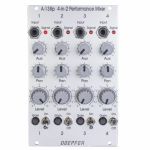
People also bought...
Doepfer A138p 4-In-2 Performance Mixer Input Module (silver) (mixer module)
Cat: 671593 Rel: 29 Nov 17 • View all Synth modules
4-in-2 performance mixer input module - 16HP
Notes: Module A-138p is the 4-fold input module.
A-138p features:
4 channels
controls and inputs for each channel
input (3.5 mm mono socket)
signal LED (as a coarse monitor of the incoming level, the level is measured after the gain control)
mute switch
gain (control to adapt different audio levels)
Level (the main volume control, linear response curve)
Aux
Pan
internal jumper for each channel to choose between Aux pre/post main Level control
internal connection to the output module and to other A-138p or A-135-4 modules
A-138p requires A-138o (no stand-alone use)
Dimensions
16 HP
40 mm deep
Current Draw
Module does not draw current
… Read moreA-138p features:
4 channels
controls and inputs for each channel
input (3.5 mm mono socket)
signal LED (as a coarse monitor of the incoming level, the level is measured after the gain control)
mute switch
gain (control to adapt different audio levels)
Level (the main volume control, linear response curve)
Aux
Pan
internal jumper for each channel to choose between Aux pre/post main Level control
internal connection to the output module and to other A-138p or A-135-4 modules
A-138p requires A-138o (no stand-alone use)
Dimensions
16 HP
40 mm deep
Current Draw
Module does not draw current
out of stock $111.05

People also bought...
Doepfer A-110-6 Trapezoid Thru Zero Quadrature VCO Module (oscillator/LFO module)
Cat: 671595 Rel: 29 Nov 17 • View all Synth modules
Trapezoid thru-zero quadrature VCO module - 12HP
Notes: A-110-6 is a Trapezoid Thru Zero Quadrature VCO. The module is based on an idea by Donald Tillman from 2003 but has been revised for the use of modern electronic circuits (no OTAs/CA3280). Because of its unique trapezoid core it's totally different compared to other VCOs. But the trapezoid core is not the only specialty: it is also a quadrature VCO and features linear thru zero frequency modulation.
The term "quadrature" means in this connection that the oscillator outputs two trapezoid waves with 90 degrees phase shift. The same as sine and cosine of a standard quadrature oscillator like the A-110-4 or A-143-9. These waveforms are called TRASIN (trapezoid sine) and TRACOS (trapezoid cosine).
The term "Thru-Zero" means that even "negative" frequencies are generated. But this a bit a misleading term as negative frequencies do not really exist. "Negative" means in this connection simply that the TRASIN/TRACOS waves will stop when the linear control voltage reaches 0V and continue with the opposite directions as the linear control voltage becomes negative and vice versa.
The module has two control sections: linear and a exponential. The exponential section consists of the XTune control, the 1V/Oct input and the XFM input with the corresponding attenuator XFM. The exponential control voltage is the sum of these three voltages. The linear section consists of the LFrq control and the LFM input with the corresponding attenuator LFM. The linear control voltage is the sum of these two voltages. A dual colour LED is used to display the polarity of the linear control voltage. The pitch of all outputs is determined by the control voltages of both sections. The linear section is used to control the pitch in a linear manner. When the LFrq control (LFrq means Linear Frequency Control) is fully CW the module works like a normal VCO and the LED lights red. The pitch is then controlled by the exponential section with the manual Tune control XTune and the exponential frequency control inputs 1V/Oct and XFM. 1V/Oct is used to control the pitch by a 1V/Oct CV source (e.g. sequencer or Midi/USB-to-CV interface). XFM is used to apply an exponential frequency modulation with adjustable depth (e.g. from an LFO or another VCO). As the LFrq control is turned counter-clockwise starting from the fully CW position the frequency is lowered in a linear manner until the TRASIN/TRACOS waves (nearly) stop at the centre position of LFrq (provided that no LFM signal is present). As the LFrq control is moved from the centre towards the CCW position the waves start again but into reverse direction and the LED turns yellow. When the fully CCW position of LFrq is reached the module works again like a normal VCO. But much more exciting is the usage of the LFM input to modify the linear control voltage by an external control voltage (typically another VCO). Linear modulation by another oscillator using the thru zero feature in combination with the trapezoid waveforms generates audio spectra than cannot be obtained from any other oscillator without the thru zero function. The reason is that a "normal" VCO will simply stop as the linear control voltage becomes zero or negative. But a thru zero VCO will start again with "negative" frequencies as the linear control voltage becomes negative.
Other waveforms like triangle, sawtooth, rectangle and sine can be obtained from the TRASIN/TRACOS signals (triangle e.g. simply by subtracting TRISIN and TRICOS, SAWSIN and SAWCOS by switching the other waveforms). All five waveforms are available as quadrature pairs (i.e. with 90 degrees phase shift):
- Trapezoid (TRASIN + TRACOS)
- Triangle (TRISIN + TRICOS)
- Sinus (SIN + COS)
- Rectangle (RECSIN + RECCOS)
- Sawtooth (SAWSIN + SAWCOS)
By means of a toggle switch the frequency range can be selected between VCO (audio range) and LFO. In LFO range the frequencies are about 1/100 compared to VCO mode.
A dual-colour LED display the polarity of the linear control section. Another dual-colour LED shows the signal TRASIN which is helpful in LFO mode.
Technical note regarding linear FM: The LFM CV input is DC coupled. If the input is used for linear FM in audio range and the signal applied to this input has a DC offset it will cause a small pitch shift that depends upon the value of the DC voltage. Especially when a VCA is used to change dynamically the level of the modulation signal this may generate a pitch shift caused by the control voltage feedthrough of the VCA. The control voltage feedthrough adds a DC voltage at the output which depends upon the control voltage of the VCA. For this application VCAs with a very low CV feed though should be used or the signal output of the VCA should be AC coupled to the LFM input of the A-110-6 (e.g. by inserting a capacitor).
Dimensions
12 HP
61 mm deep
Current draw
80 mA +12V
70 mA -12V
… Read moreThe term "quadrature" means in this connection that the oscillator outputs two trapezoid waves with 90 degrees phase shift. The same as sine and cosine of a standard quadrature oscillator like the A-110-4 or A-143-9. These waveforms are called TRASIN (trapezoid sine) and TRACOS (trapezoid cosine).
The term "Thru-Zero" means that even "negative" frequencies are generated. But this a bit a misleading term as negative frequencies do not really exist. "Negative" means in this connection simply that the TRASIN/TRACOS waves will stop when the linear control voltage reaches 0V and continue with the opposite directions as the linear control voltage becomes negative and vice versa.
The module has two control sections: linear and a exponential. The exponential section consists of the XTune control, the 1V/Oct input and the XFM input with the corresponding attenuator XFM. The exponential control voltage is the sum of these three voltages. The linear section consists of the LFrq control and the LFM input with the corresponding attenuator LFM. The linear control voltage is the sum of these two voltages. A dual colour LED is used to display the polarity of the linear control voltage. The pitch of all outputs is determined by the control voltages of both sections. The linear section is used to control the pitch in a linear manner. When the LFrq control (LFrq means Linear Frequency Control) is fully CW the module works like a normal VCO and the LED lights red. The pitch is then controlled by the exponential section with the manual Tune control XTune and the exponential frequency control inputs 1V/Oct and XFM. 1V/Oct is used to control the pitch by a 1V/Oct CV source (e.g. sequencer or Midi/USB-to-CV interface). XFM is used to apply an exponential frequency modulation with adjustable depth (e.g. from an LFO or another VCO). As the LFrq control is turned counter-clockwise starting from the fully CW position the frequency is lowered in a linear manner until the TRASIN/TRACOS waves (nearly) stop at the centre position of LFrq (provided that no LFM signal is present). As the LFrq control is moved from the centre towards the CCW position the waves start again but into reverse direction and the LED turns yellow. When the fully CCW position of LFrq is reached the module works again like a normal VCO. But much more exciting is the usage of the LFM input to modify the linear control voltage by an external control voltage (typically another VCO). Linear modulation by another oscillator using the thru zero feature in combination with the trapezoid waveforms generates audio spectra than cannot be obtained from any other oscillator without the thru zero function. The reason is that a "normal" VCO will simply stop as the linear control voltage becomes zero or negative. But a thru zero VCO will start again with "negative" frequencies as the linear control voltage becomes negative.
Other waveforms like triangle, sawtooth, rectangle and sine can be obtained from the TRASIN/TRACOS signals (triangle e.g. simply by subtracting TRISIN and TRICOS, SAWSIN and SAWCOS by switching the other waveforms). All five waveforms are available as quadrature pairs (i.e. with 90 degrees phase shift):
- Trapezoid (TRASIN + TRACOS)
- Triangle (TRISIN + TRICOS)
- Sinus (SIN + COS)
- Rectangle (RECSIN + RECCOS)
- Sawtooth (SAWSIN + SAWCOS)
By means of a toggle switch the frequency range can be selected between VCO (audio range) and LFO. In LFO range the frequencies are about 1/100 compared to VCO mode.
A dual-colour LED display the polarity of the linear control section. Another dual-colour LED shows the signal TRASIN which is helpful in LFO mode.
Technical note regarding linear FM: The LFM CV input is DC coupled. If the input is used for linear FM in audio range and the signal applied to this input has a DC offset it will cause a small pitch shift that depends upon the value of the DC voltage. Especially when a VCA is used to change dynamically the level of the modulation signal this may generate a pitch shift caused by the control voltage feedthrough of the VCA. The control voltage feedthrough adds a DC voltage at the output which depends upon the control voltage of the VCA. For this application VCAs with a very low CV feed though should be used or the signal output of the VCA should be AC coupled to the LFM input of the A-110-6 (e.g. by inserting a capacitor).
Dimensions
12 HP
61 mm deep
Current draw
80 mA +12V
70 mA -12V
out of stock $221.06

People also bought...
Doepfer A-190-4 USB MIDI To CV & Gate Interface Module (synth module)
Cat: 671598 Rel: 29 Nov 17 • View all Synth modules
Monophonic MIDI/USB interface Eurorack module with outputs for gate, clock, reset & two outputs for CV's
Notes: A-190-4 is the replacement for module A-190-1 which is no longer available. The functions of A-190-1 and A-190-4 are nearly the same (Midi In, Midi Out, CV1, CV2, Gate, Clock, Reset). But the operation of the A-190-4 has been improved because a 3-digit LED display is available. The current values of all parameters (like Midi channel, reference note, clock divider) can be read back and modified by means of up/down buttons. In addition, A-190-4 is equipped with an USB interface and the external +5V supply is no longer available. Consequently, the additional charges for the 5V adapter fall away.
The module width is the same for A-190-1 and A-190-4. In the A-100 basic systems the A-190-1 will be replaced by the A-190-4 from about May 2014.
Important notes:
- The Scale (SCA) and Tune (TUn) parameters remain unchanged when the module is initialized! Otherwise the initialization would overwrite the adjusted values. Because of the tolerances of electrical parts there are no fixed values for SCA and TUn which are valid for all modules. The values for SCA and TUn differ a bit from module to module because of the tolerances of electrical parts. In case that the module has been adjusted totally wrong: typical values are 100 for SCA (coarse) and 55 for TUn (coarse).
- The module comes with installed bus jumpers for CV and Gate. One has to remove the jumpers if e.g. an A-164, A-190-1, A-190-2, A-190-3, A-185-1 or A-185-2 is already connected to the CV and/or gate lines of the same bus board! If the A-190-3 should be used as CV and gate source for the A-100 bus the CV and gate connections of other CV/gate sources to the A-100 bus have to be removed. Otherwise short circuits are made between the outputs of the CV or gate transmitters!
- The gate level of the A-190-3 can be changed from +5V to +12V. For this the jumper on JP10A (behind the CV Note socket, labelled "GATE 5V JP10A") has to be removed and installed to JP10B (behind the 16 pin bus connector, labelled "GATE 12V JP10B").
- The module is a USB device or slave in USB mode. It has no USB host function (like computers or laptops with type A USB connectors).
… Read moreThe module width is the same for A-190-1 and A-190-4. In the A-100 basic systems the A-190-1 will be replaced by the A-190-4 from about May 2014.
Important notes:
- The Scale (SCA) and Tune (TUn) parameters remain unchanged when the module is initialized! Otherwise the initialization would overwrite the adjusted values. Because of the tolerances of electrical parts there are no fixed values for SCA and TUn which are valid for all modules. The values for SCA and TUn differ a bit from module to module because of the tolerances of electrical parts. In case that the module has been adjusted totally wrong: typical values are 100 for SCA (coarse) and 55 for TUn (coarse).
- The module comes with installed bus jumpers for CV and Gate. One has to remove the jumpers if e.g. an A-164, A-190-1, A-190-2, A-190-3, A-185-1 or A-185-2 is already connected to the CV and/or gate lines of the same bus board! If the A-190-3 should be used as CV and gate source for the A-100 bus the CV and gate connections of other CV/gate sources to the A-100 bus have to be removed. Otherwise short circuits are made between the outputs of the CV or gate transmitters!
- The gate level of the A-190-3 can be changed from +5V to +12V. For this the jumper on JP10A (behind the CV Note socket, labelled "GATE 5V JP10A") has to be removed and installed to JP10B (behind the 16 pin bus connector, labelled "GATE 12V JP10B").
- The module is a USB device or slave in USB mode. It has no USB host function (like computers or laptops with type A USB connectors).
out of stock $165.02

People also bought...
Doepfer A-138o Performance Mixer Output Module (silver) (mixer/utility/expander module)
Cat: 671600 Rel: 29 Nov 17 • View all Synth modules
Performance mixer output module - 4HP
Notes: Modules A-138p/o are used to build a simple performance mixer (instead of an external stand-alone mixer). Module A-138p is the 4-fold input module, A-138o is the output module that can be combined with one or more A-138p.
A-138o features:
- Level controls for Left, Right and Aux
- Output sockets for Left, Right and Aux (3.5 mm mono sockets)
- A-138o requires at least one A-138p (no stand-alone use)
- Application example for Aux Send and Aux Return: looping in another module for effects (e.g. DSP module A-187-1, BBD module A-188-1, Spring Reverb A-199)
- Application example for Aux Send only: pre-listening in combination with the headphone amplifier module A-139-2
- 3U Eurorack module, 4HP wide, 40mm deep
- Current draw: 20mA at +12V and 12V at -12V
… Read moreA-138o features:
- Level controls for Left, Right and Aux
- Output sockets for Left, Right and Aux (3.5 mm mono sockets)
- A-138o requires at least one A-138p (no stand-alone use)
- Application example for Aux Send and Aux Return: looping in another module for effects (e.g. DSP module A-187-1, BBD module A-188-1, Spring Reverb A-199)
- Application example for Aux Send only: pre-listening in combination with the headphone amplifier module A-139-2
- 3U Eurorack module, 4HP wide, 40mm deep
- Current draw: 20mA at +12V and 12V at -12V
out of stock $55.00

People also bought...
Doepfer A-155 Analogue Trigger Sequencer Module (silver) (sequencer synth module)
Cat: 671601 Rel: 29 Nov 17 • View all Synth modules
Analogue sequencer for CV's & trigger/gates
Notes: The Doepfer A-155 has two CV rows, each with selectable voltage range, glide and sample & hold options. Three trigger rows and a one gate row. Logic inputs for clock, reset, start and stop. It's even possible to insert external signals per step instead, overriding the CV generated by the 2nd row's potentiometer. The A-155's functions can be expanded by the A-154 Sequencer Controller, as it's an entire control unit with step number limitation, voltage controllable clock generator, variable gate length and a number of playback modes.
Features of the analogue rows (knobs):
- 8 potentiometers (knobs)
- Lower row: Scale (knob), voltage output range 0 ... ~ +6,5V
- Upper row: 1V/2V/4V (octave range switch for exact VCO control), voltage output ranges 0 ...1.0V / 0 ...2.0V / 0 ...4.0V
- Glide time (knob), same as portamento or slew limiter
- Glide Control (control input for switching glide on/off)
- S&H Control (control input for internal S&H, works like A-148)
- Pre Glide/S&H-Out (analogue output before S&H and glide unit, especially required when external audio signals are used as inputs of the lower row)
- Post Glide/S&H-Out (analogue output after S&H and glide unit)
- Lower row: external inputs for the 8 steps (switched jack sockets), control signals or audio signals may be used as inputs (allowed voltage range -5V...+12V), the knobs of the lower row are working in this case as attenuators
Features of the trigger rows (switches):
- 4 Trigger/Gate tracks with 2 rows of switches
- Toggle switches of 1-0-1 type (with middle position), which can be used to send a trigger/gate to the track above or below or to send no trigger/gate (middle position)
- 3 trigger rows (i.e. short pulse for each step set, pulse width corresponds to the pulse width of the clock/step input signal)
- 1 gate row (i.e. a high signal is applied during the length of the step set)
Control inputs and buttons:
- Step (defines the tempo of the sequence, same as clock or trigger input)
- Reset (resets all rows to step 1)
- Start (starts the sequence at the momentary position)
- Stop (stops the sequence at the momentary position)
Step and Reset are compatible to the MIDI interface A-190, i.e. in combination with the A-190 the A-155 may be synchronized via MIDI. The quantizing module A-156 can be used to quantize the infinite analogue voltages coming from A-155 into discrete semitone steps (multiples of 1/12V). Without MIDI interface e.g. a LFO rectangle output can be used to define the tempo of the sequence.
The sequencer controller A-154 adds a lot of new functions to the A-155 (e.g. voltage controlled addressing, forward/backward/pendulum/random mode, voltage control of first and last step, voltage controlled clock and gate length, step skipping, combination of several A-155 in parallel/serial mode and many more).
… Read moreFeatures of the analogue rows (knobs):
- 8 potentiometers (knobs)
- Lower row: Scale (knob), voltage output range 0 ... ~ +6,5V
- Upper row: 1V/2V/4V (octave range switch for exact VCO control), voltage output ranges 0 ...1.0V / 0 ...2.0V / 0 ...4.0V
- Glide time (knob), same as portamento or slew limiter
- Glide Control (control input for switching glide on/off)
- S&H Control (control input for internal S&H, works like A-148)
- Pre Glide/S&H-Out (analogue output before S&H and glide unit, especially required when external audio signals are used as inputs of the lower row)
- Post Glide/S&H-Out (analogue output after S&H and glide unit)
- Lower row: external inputs for the 8 steps (switched jack sockets), control signals or audio signals may be used as inputs (allowed voltage range -5V...+12V), the knobs of the lower row are working in this case as attenuators
Features of the trigger rows (switches):
- 4 Trigger/Gate tracks with 2 rows of switches
- Toggle switches of 1-0-1 type (with middle position), which can be used to send a trigger/gate to the track above or below or to send no trigger/gate (middle position)
- 3 trigger rows (i.e. short pulse for each step set, pulse width corresponds to the pulse width of the clock/step input signal)
- 1 gate row (i.e. a high signal is applied during the length of the step set)
Control inputs and buttons:
- Step (defines the tempo of the sequence, same as clock or trigger input)
- Reset (resets all rows to step 1)
- Start (starts the sequence at the momentary position)
- Stop (stops the sequence at the momentary position)
Step and Reset are compatible to the MIDI interface A-190, i.e. in combination with the A-190 the A-155 may be synchronized via MIDI. The quantizing module A-156 can be used to quantize the infinite analogue voltages coming from A-155 into discrete semitone steps (multiples of 1/12V). Without MIDI interface e.g. a LFO rectangle output can be used to define the tempo of the sequence.
The sequencer controller A-154 adds a lot of new functions to the A-155 (e.g. voltage controlled addressing, forward/backward/pendulum/random mode, voltage control of first and last step, voltage controlled clock and gate length, step skipping, combination of several A-155 in parallel/serial mode and many more).
out of stock $265.53

People also bought...
Doepfer A-112 VC Sampler & Wavetable Oscillator Module (silver) (oscillator/sampling/digital synth module)
Cat: 671607 Rel: 29 Nov 17 • View all Synth modules
Combined module of voltage-controlled 8-bit sampler & wavetable oscillator, 10HP
Notes: Module A-112 is the combination of a voltage controlled 8 Bit Sampler and a wavetable oscillator. On top of it the module is able to generate some special effects. A-112 was designed as an additional sound source with the typical sounds of the early 8 bit samplers and is not comparable with the modern polyphonic MIDI samplers available on the market.
Sampling mode: 8 bit audio resolution, 128kB memory in 2 banks 64kB each (equivalent to 2 seconds of sampling time for each bank with 32 kHz sampling rate), audio input with attenuator, overload display in record mode (gate LED), possibility of MIDI Dump to store sounds in a computer via MIDI, non-volatile memory for the 2 samples in the module, manual tune control for adjustment of sampling rate for record and play, CV input (~ 1V/Oct), both manual tune and CV determine the sampling rate respectively the pitch (pitch range is 5 octaves), gate input (not a trigger: the sample starts at the positive edge of the gate signal and is played as long as gate is high or until the end of the sample is reached), manual Gate button, non-filtered audio output (thus quantizing noise can be used as an element of the sound intentionally).
Wavetable mode: special appearance of the sampling mode when playing a sample, the audio input is now used as a second control voltage input for moving through the sample in 256 byte wide loops (wavetables). The control voltage required to move through all wavetables applied to the input "Wave CV In" is in the range -2.5V (wavetable 1) ... 0V (wavetable 127) ... +2.5V (wavetable 256) when control "Atten." is set fully clockwise. To achieve the typical wavetable oscillator sounds the sampling memory must contain corresponding wavetable data (e.g. loaded via MIDI dump). These data contain a set of wavetables with different harmonic content (e.g. a filter sweep) to get the typical wavetable sound while moving through the tables via CV. But you may also use a "normal" sample and go through the sample with CV to obtain partially amazing sounds never heard before. You may use for example sampled speech and go with CV through the syllables or speech shreds to get really very extreme sounds. An ideal addition for this feature is the Offset/Attenuator module A-183-2 which can be used to adjust the position of the wavetable (Offset) and the modulation depth (Att.). The corresponding jumper of the A-183-2 has to be set to bipolar offset (as the A-112 requires -2.5V...+2.5V to pass through all 256 wavetables). As modulation source an LFO (A-145, A-146, A-147, A-143-3), ADSR (A-140, A-141, A-142, A-143-1/2) or a random voltage (A-118, A-149-1) may be used. Even a ribbon controller (A-198 or R2M), the Theremin module A-178, the Joystick A-174 or the Wheels module A-174-2 are useful to drive through the wavetables.
Effects: Additionally, the module offers - in a way free of charge - some effects like delay, reverse delay, pitch shifting or freeze. But it has to be pointed out that due to the 8 bit audio resolution these effects are not comparable to high quality effect units and should be understand as an extra for nothing. The A-112 is not an effects unit!
The sampling time of the A-112 is about 1...30 seconds corresponding to a sampling frequency range of about 60kHz...2kHz (64kB@60kHz ~ 1 s, 64kB@2kHz ~ 30 s).
Technical note: the module uses a battery for the non-volatile storage of the sampling data. Batteries have a limited lifespan and have to be inspected at least every two years. For details please refer to the FAQ page of our website: Lifespan of rechargeable batteries (used for memory backup).
… Read moreSampling mode: 8 bit audio resolution, 128kB memory in 2 banks 64kB each (equivalent to 2 seconds of sampling time for each bank with 32 kHz sampling rate), audio input with attenuator, overload display in record mode (gate LED), possibility of MIDI Dump to store sounds in a computer via MIDI, non-volatile memory for the 2 samples in the module, manual tune control for adjustment of sampling rate for record and play, CV input (~ 1V/Oct), both manual tune and CV determine the sampling rate respectively the pitch (pitch range is 5 octaves), gate input (not a trigger: the sample starts at the positive edge of the gate signal and is played as long as gate is high or until the end of the sample is reached), manual Gate button, non-filtered audio output (thus quantizing noise can be used as an element of the sound intentionally).
Wavetable mode: special appearance of the sampling mode when playing a sample, the audio input is now used as a second control voltage input for moving through the sample in 256 byte wide loops (wavetables). The control voltage required to move through all wavetables applied to the input "Wave CV In" is in the range -2.5V (wavetable 1) ... 0V (wavetable 127) ... +2.5V (wavetable 256) when control "Atten." is set fully clockwise. To achieve the typical wavetable oscillator sounds the sampling memory must contain corresponding wavetable data (e.g. loaded via MIDI dump). These data contain a set of wavetables with different harmonic content (e.g. a filter sweep) to get the typical wavetable sound while moving through the tables via CV. But you may also use a "normal" sample and go through the sample with CV to obtain partially amazing sounds never heard before. You may use for example sampled speech and go with CV through the syllables or speech shreds to get really very extreme sounds. An ideal addition for this feature is the Offset/Attenuator module A-183-2 which can be used to adjust the position of the wavetable (Offset) and the modulation depth (Att.). The corresponding jumper of the A-183-2 has to be set to bipolar offset (as the A-112 requires -2.5V...+2.5V to pass through all 256 wavetables). As modulation source an LFO (A-145, A-146, A-147, A-143-3), ADSR (A-140, A-141, A-142, A-143-1/2) or a random voltage (A-118, A-149-1) may be used. Even a ribbon controller (A-198 or R2M), the Theremin module A-178, the Joystick A-174 or the Wheels module A-174-2 are useful to drive through the wavetables.
Effects: Additionally, the module offers - in a way free of charge - some effects like delay, reverse delay, pitch shifting or freeze. But it has to be pointed out that due to the 8 bit audio resolution these effects are not comparable to high quality effect units and should be understand as an extra for nothing. The A-112 is not an effects unit!
The sampling time of the A-112 is about 1...30 seconds corresponding to a sampling frequency range of about 60kHz...2kHz (64kB@60kHz ~ 1 s, 64kB@2kHz ~ 30 s).
Technical note: the module uses a battery for the non-volatile storage of the sampling data. Batteries have a limited lifespan and have to be inspected at least every two years. For details please refer to the FAQ page of our website: Lifespan of rechargeable batteries (used for memory backup).
out of stock $138.04
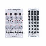
People also bought...
Doepfer A-135-4A/B VC Performance Mixer Input & Control Modules (single) (mixer/panning/quad/expander synth module)
Cat: 671608 Rel: 29 Nov 17 • View all Synth modules
Voltage controllable performance mixer module package
Notes: Series A-135-4 contains several modules which are used to built a voltage controlled performance mixer. The modules of the A-135-4 series can be combined with the (non voltage controlled) mixer modules A-138o/p.
A-135-4A:
A-135-4A is the main module. It is very similar to module A-138p, but with voltage control for all parameters (except gain). Also the front panels of A-135-4A and A-138p are very similar. The only difference are the additional LEDs which are used to display the magnitudes of all voltage controlled parameters. This is necessary because the positions of the manual controls do not necessarily correspond to the resulting parameter value because these are composed by both the manual controls and the applied external control voltages (via A-135-4B). Without LEDs one would be left in the dark in regard to the actual parameter value.
A-135-4A contains four high quality voltage controlled amplifiers (VCA) for each channel: one for the main level, two for panorama left/right and one for aux. The control scales for all parameters are linear. Altogether 16 VCAs are included in the module. High end linear VCAs manufactured by Curtis/USA are used (CEM3381). The 16 LEDs display roughly the amplification of the VCA in question.
Module A-138o is used as output module for the A-135-4A. A-135-4A and A-138p can be connected together to the same A-138o to obtain e.g. four fully voltage controlled channels (A-135-4A) and four manually controlled channels (A-138p).
A-135-4B:
This module is used to route the 16 external control voltage to the main module A-135-4A. These control voltages are available for each channel:
- Level (main loudness)
- Panorama
- Aux
- Mute
Each control voltage has an input socket and a polarizer control available (the polarizer function is described more detailed on the A-138c info page). That way it's possible to adjust the depth and polarity of the external control voltage which affects the parameter in question. If the same CV (e.g. LFO or ADSR) is used e.g. for two panorama control inputs the result may be the opposite if the polarizers are adjusted accordingly (i.e. one positive and the other negative). The external control voltage is added to the voltage that is generated by the manual control on the A-135-4A main module. The sum of both voltages is used to control the VCA in question and is displayed with the corresponding LED on the A-135-4A module. The picture on the left side below shows one channel of A-135-4A/B as block diagram.
The mute CV input works in principle in the same way as the level CV input but with reverse polarity and higher sensitivity (about factor -2). Typically, the mute polarizer control is adjusted fully CW. Then a (gate) voltage of ~ +2.5V or more fully mutes the channel in question. If the mute function is not used the mute CV input can be used as a second CV input for level (with twice the sensitivity and inverted polarity compared to the normal level CV input).
A-135-4A and A-135-4B are connected internally via a 20 pin ribbon cable. The cable can be longer so that the CV input module A-135-4B needs not to be mounted next to the main module A-135-4A (e.g. to the row above or below).
Modules A-135-4A and A-135-4B are available only as a module combo because the single operation of each module does not make sense!
… Read moreA-135-4A:
A-135-4A is the main module. It is very similar to module A-138p, but with voltage control for all parameters (except gain). Also the front panels of A-135-4A and A-138p are very similar. The only difference are the additional LEDs which are used to display the magnitudes of all voltage controlled parameters. This is necessary because the positions of the manual controls do not necessarily correspond to the resulting parameter value because these are composed by both the manual controls and the applied external control voltages (via A-135-4B). Without LEDs one would be left in the dark in regard to the actual parameter value.
A-135-4A contains four high quality voltage controlled amplifiers (VCA) for each channel: one for the main level, two for panorama left/right and one for aux. The control scales for all parameters are linear. Altogether 16 VCAs are included in the module. High end linear VCAs manufactured by Curtis/USA are used (CEM3381). The 16 LEDs display roughly the amplification of the VCA in question.
Module A-138o is used as output module for the A-135-4A. A-135-4A and A-138p can be connected together to the same A-138o to obtain e.g. four fully voltage controlled channels (A-135-4A) and four manually controlled channels (A-138p).
A-135-4B:
This module is used to route the 16 external control voltage to the main module A-135-4A. These control voltages are available for each channel:
- Level (main loudness)
- Panorama
- Aux
- Mute
Each control voltage has an input socket and a polarizer control available (the polarizer function is described more detailed on the A-138c info page). That way it's possible to adjust the depth and polarity of the external control voltage which affects the parameter in question. If the same CV (e.g. LFO or ADSR) is used e.g. for two panorama control inputs the result may be the opposite if the polarizers are adjusted accordingly (i.e. one positive and the other negative). The external control voltage is added to the voltage that is generated by the manual control on the A-135-4A main module. The sum of both voltages is used to control the VCA in question and is displayed with the corresponding LED on the A-135-4A module. The picture on the left side below shows one channel of A-135-4A/B as block diagram.
The mute CV input works in principle in the same way as the level CV input but with reverse polarity and higher sensitivity (about factor -2). Typically, the mute polarizer control is adjusted fully CW. Then a (gate) voltage of ~ +2.5V or more fully mutes the channel in question. If the mute function is not used the mute CV input can be used as a second CV input for level (with twice the sensitivity and inverted polarity compared to the normal level CV input).
A-135-4A and A-135-4B are connected internally via a 20 pin ribbon cable. The cable can be longer so that the CV input module A-135-4B needs not to be mounted next to the main module A-135-4A (e.g. to the row above or below).
Modules A-135-4A and A-135-4B are available only as a module combo because the single operation of each module does not make sense!
out of stock $375.72
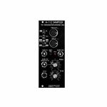
People also bought...
Doepfer A-112v Sampler VC Sampler & Wavetable Oscillator Vintage Edition Module (black) (delay/digital/oscillator/sampling synth module)
Cat: 671610 Rel: 29 Nov 17 • View all Synth modules
Combined module of voltage-controlled 8-bit sampler & wavetable oscillator - vintage edition, 10HP
Notes: Module A-112 is the combination of a voltage controlled 8 Bit Sampler and a wavetable oscillator. On top of it the module is able to generate some special effects. A-112 was designed as an additional sound source with the typical sounds of the early 8 bit samplers and is not comparable with the modern polyphonic MIDI samplers available on the market.
Sampling mode: 8 bit audio resolution, 128kB memory in 2 banks 64kB each (equivalent to 2 seconds of sampling time for each bank with 32 kHz sampling rate), audio input with attenuator, overload display in record mode (gate LED), possibility of MIDI Dump to store sounds in a computer via MIDI, non-volatile memory for the 2 samples in the module, manual tune control for adjustment of sampling rate for record and play, CV input (~ 1V/Oct), both manual tune and CV determine the sampling rate respectively the pitch (pitch range is 5 octaves), gate input (not a trigger: the sample starts at the positive edge of the gate signal and is played as long as gate is high or until the end of the sample is reached), manual Gate button, non-filtered audio output (thus quantizing noise can be used as an element of the sound intentionally).
Wavetable mode: special appearance of the sampling mode when playing a sample, the audio input is now used as a second control voltage input for moving through the sample in 256 byte wide loops (wavetables). The control voltage required to move through all wavetables applied to the input "Wave CV In" is in the range -2.5V (wavetable 1) ... 0V (wavetable 127) ... +2.5V (wavetable 256) when control "Atten." is set fully clockwise. To achieve the typical wavetable oscillator sounds the sampling memory must contain corresponding wavetable data (e.g. loaded via MIDI dump). These data contain a set of wavetables with different harmonic content (e.g. a filter sweep) to get the typical wavetable sound while moving through the tables via CV. But you may also use a "normal" sample and go through the sample with CV to obtain partially amazing sounds never heard before. You may use for example sampled speech and go with CV through the syllables or speech shreds to get really very extreme sounds. An ideal addition for this feature is the Offset/Attenuator module A-183-2 which can be used to adjust the position of the wavetable (Offset) and the modulation depth (Att.). The corresponding jumper of the A-183-2 has to be set to bipolar offset (as the A-112 requires -2.5V...+2.5V to pass through all 256 wavetables). As modulation source an LFO (A-145, A-146, A-147, A-143-3), ADSR (A-140, A-141, A-142, A-143-1/2) or a random voltage (A-118, A-149-1) may be used. Even a ribbon controller (A-198 or R2M), the Theremin module A-178, the Joystick A-174 or the Wheels module A-174-2 are useful to drive through the wavetables.
Effects: Additionally, the module offers - in a way free of charge - some effects like delay, reverse delay, pitch shifting or freeze. But it has to be pointed out that due to the 8 bit audio resolution these effects are not comparable to high quality effect units and should be understand as an extra for nothing. The A-112 is not an effects unit!
The sampling time of the A-112 is about 1...30 seconds corresponding to a sampling frequency range of about 60kHz...2kHz (64kB@60kHz ~ 1 s, 64kB@2kHz ~ 30 s).
Technical note: the module uses a battery for the non-volatile storage of the sampling data. Batteries have a limited lifespan and have to be inspected at least every two years. For details please refer to the FAQ page of our website: Lifespan of rechargeable batteries (used for memory backup).
… Read moreSampling mode: 8 bit audio resolution, 128kB memory in 2 banks 64kB each (equivalent to 2 seconds of sampling time for each bank with 32 kHz sampling rate), audio input with attenuator, overload display in record mode (gate LED), possibility of MIDI Dump to store sounds in a computer via MIDI, non-volatile memory for the 2 samples in the module, manual tune control for adjustment of sampling rate for record and play, CV input (~ 1V/Oct), both manual tune and CV determine the sampling rate respectively the pitch (pitch range is 5 octaves), gate input (not a trigger: the sample starts at the positive edge of the gate signal and is played as long as gate is high or until the end of the sample is reached), manual Gate button, non-filtered audio output (thus quantizing noise can be used as an element of the sound intentionally).
Wavetable mode: special appearance of the sampling mode when playing a sample, the audio input is now used as a second control voltage input for moving through the sample in 256 byte wide loops (wavetables). The control voltage required to move through all wavetables applied to the input "Wave CV In" is in the range -2.5V (wavetable 1) ... 0V (wavetable 127) ... +2.5V (wavetable 256) when control "Atten." is set fully clockwise. To achieve the typical wavetable oscillator sounds the sampling memory must contain corresponding wavetable data (e.g. loaded via MIDI dump). These data contain a set of wavetables with different harmonic content (e.g. a filter sweep) to get the typical wavetable sound while moving through the tables via CV. But you may also use a "normal" sample and go through the sample with CV to obtain partially amazing sounds never heard before. You may use for example sampled speech and go with CV through the syllables or speech shreds to get really very extreme sounds. An ideal addition for this feature is the Offset/Attenuator module A-183-2 which can be used to adjust the position of the wavetable (Offset) and the modulation depth (Att.). The corresponding jumper of the A-183-2 has to be set to bipolar offset (as the A-112 requires -2.5V...+2.5V to pass through all 256 wavetables). As modulation source an LFO (A-145, A-146, A-147, A-143-3), ADSR (A-140, A-141, A-142, A-143-1/2) or a random voltage (A-118, A-149-1) may be used. Even a ribbon controller (A-198 or R2M), the Theremin module A-178, the Joystick A-174 or the Wheels module A-174-2 are useful to drive through the wavetables.
Effects: Additionally, the module offers - in a way free of charge - some effects like delay, reverse delay, pitch shifting or freeze. But it has to be pointed out that due to the 8 bit audio resolution these effects are not comparable to high quality effect units and should be understand as an extra for nothing. The A-112 is not an effects unit!
The sampling time of the A-112 is about 1...30 seconds corresponding to a sampling frequency range of about 60kHz...2kHz (64kB@60kHz ~ 1 s, 64kB@2kHz ~ 30 s).
Technical note: the module uses a battery for the non-volatile storage of the sampling data. Batteries have a limited lifespan and have to be inspected at least every two years. For details please refer to the FAQ page of our website: Lifespan of rechargeable batteries (used for memory backup).
1 in stock $171.24
Click for better price!
or call +44 20 7424 1960
quote 671610
quote 671610

People also bought...
Doepfer A-138b 4-Channel Mixer Logarithmic Module (silver) (mixer/quad synth module)
Cat: 577776 Rel: 29 Nov 17 • View all Synth modules
Four channel mixer module - 8HP
Notes: Module A-138 is a four channel mixer, which can be used with either control voltages or audio signals. Each of the four inputs has an attenuator, and there's a master attenuator, so that the mixer can be used at the end of the audio chain, i.e. it can be used to interface directly with an external mixer, amplifier, etc.
The A-138b has potentiometers with logarithmic response, so is especially suitable for audio signal mixing.
… Read moreThe A-138b has potentiometers with logarithmic response, so is especially suitable for audio signal mixing.
out of stock $50.88

People also bought...
Doepfer A-140 ADSR Envelope Generator Module (silver) (envelope generator synth module)
Cat: 577754 Rel: 29 Nov 17 • View all Synth modules
Envelope generator with CV outputs for modulation - 8HP
Notes: Module A-140 is an envelope generator, and, since it puts out control voltages, counts as one of the modulation devices in a modular system. As soon as the gate input receives sufficient voltage, the ADSR generates a variable voltage, changing in time, called an envelope. This varying voltage is output in normal (positive) and inverted form, and can be used, eg. for voltage controlled modulation of a VCO, VCF, or VCA, or for processing other modules' inputs and outputs.
The shape of the envelope is governed by four parameters: Attack, Decay, Sustain and Release.
The envelope is started (triggered) by a gate signal either from the INT.GATE voltage on the system bus, or, if a signal is put into it, from the gate input socket.
The envelope can also be re-triggered, i.e. start from scratch again, each time a trigger signal is sensed at the Retrig. input socket, when the gate is still open.
Module A-140 has available a three-position toggle switch to select one of three time ranges. The envelope duration ranges from about 50us (microseconds) up to several minutes.
In combination with the Comparator module A-167 a free-running "ADSR-LFO" can be realized.
… Read moreThe shape of the envelope is governed by four parameters: Attack, Decay, Sustain and Release.
The envelope is started (triggered) by a gate signal either from the INT.GATE voltage on the system bus, or, if a signal is put into it, from the gate input socket.
The envelope can also be re-triggered, i.e. start from scratch again, each time a trigger signal is sensed at the Retrig. input socket, when the gate is still open.
Module A-140 has available a three-position toggle switch to select one of three time ranges. The envelope duration ranges from about 50us (microseconds) up to several minutes.
In combination with the Comparator module A-167 a free-running "ADSR-LFO" can be realized.
out of stock $74.72

People also bought...
Doepfer A-124 VCF5 Wasp Filter 12db/Oct Multimode Filter Module (silver) (filter synth module)
Cat: 577743 Rel: 29 Nov 17 • View all Synth modules
12dB multimode filter module - 8HP
Notes: Module A-124 is a special 12dB multimode filter using the "strange" filter circuit of the "EDP Wasp" (an analog synthesizer with black/yellow case built end of the seventies, manufactured by the UK company "Electronic Dream Plant").
This design "abuses" digital inverters as analog operational amplifiers leading to distortions and other "dirty" effects that generate the specific sound of this filter.
The filter is equipped with a band pass output and a combined low/notch/high pass output. For this output a control knob defines the relation between low and high pass signal.
If both signals appear at the same level (i.e. middle position of the Mix knob) one obtains a notch filter. Otherwise the low or high pass signal predominates.
The module does not feature self oscillation in contrast to most of the other filters of the A-100 system.
… Read moreThis design "abuses" digital inverters as analog operational amplifiers leading to distortions and other "dirty" effects that generate the specific sound of this filter.
The filter is equipped with a band pass output and a combined low/notch/high pass output. For this output a control knob defines the relation between low and high pass signal.
If both signals appear at the same level (i.e. middle position of the Mix knob) one obtains a notch filter. Otherwise the low or high pass signal predominates.
The module does not feature self oscillation in contrast to most of the other filters of the A-100 system.
out of stock $82.78

People also bought...
Doepfer A-110-1 Standard VCO Module (synth module)
Cat: 577769 Rel: 29 Nov 17 • View all Synth modules
Standard VCO providing two CV inputs for pitch, an octave switch, four waveforms with separate outputs, pulse width modulation & hard sync - 10HP
Notes: Module A-110-1 is a voltage-controlled oscillator. This VCO's frequency range is about eight octaves (ca. 15Hz ... 8kHz). It can produce four waveforms simultaneously: rectangle, sawtooth, triangle, and sine wave (triangle and sine shapes are not perfect, see remark below). The output levels are typically 8Vpp for saw and rectangle, and 10Vpp for triangle and sine. The frequency or pitch of the VCO is determined by the position of the octave (Range) switch and tuning (Tune) knob, and by the voltage present at the CV inputs. Frequency modulation (FM) of the VCO is therefore a possibility. Footage (the octave of the fundamental) is set by the Range control in five steps, and Fine tuning controlled by the Tune knob by about +/-1 one semitone (can be modified for a wider range).
You can control the pulse width of the square wave either by hand, or by voltage control - Pulse Width Modulation or PWM.
For more detailed information please look at the user's manual A110_man.pdf. In addition, the A-110 service manual is available as an example for the A-100 service manual that is available at extra charges. This document describes also how to modify the sensitivity of the tune control, how to re-adjust the 1V/octave scale and the frequency offset (i.e. the absolute pitch). Such modifications should be carried out by experienced users only!
The core of the A-110-1 is a sawtooth oscillator (in contrast to the A-111-1, which is based on a triangle oscillator). The other waveforms are derived from the sawtooth by internal waveform converters. As the sawtooth reset (i.e. the back-to-zero slope) is not infinite fast but takes a little bit of time the derived waveforms triangle and sine are not perfect! At the top of the waveform they have a small glitch or notch that is caused by the sawtooth reset and cannot be eliminated by the waveform converters. The sine is derived from the triangle by a simple diode-based converter and the sine shape is not perfect (only a rounded triangle).
If a perfect triangle is required, the A-111-1 is recommended. For a perfect sine wave the quadrature LFO/VCO A-143-9 is recommended.
… Read moreYou can control the pulse width of the square wave either by hand, or by voltage control - Pulse Width Modulation or PWM.
For more detailed information please look at the user's manual A110_man.pdf. In addition, the A-110 service manual is available as an example for the A-100 service manual that is available at extra charges. This document describes also how to modify the sensitivity of the tune control, how to re-adjust the 1V/octave scale and the frequency offset (i.e. the absolute pitch). Such modifications should be carried out by experienced users only!
The core of the A-110-1 is a sawtooth oscillator (in contrast to the A-111-1, which is based on a triangle oscillator). The other waveforms are derived from the sawtooth by internal waveform converters. As the sawtooth reset (i.e. the back-to-zero slope) is not infinite fast but takes a little bit of time the derived waveforms triangle and sine are not perfect! At the top of the waveform they have a small glitch or notch that is caused by the sawtooth reset and cannot be eliminated by the waveform converters. The sine is derived from the triangle by a simple diode-based converter and the sine shape is not perfect (only a rounded triangle).
If a perfect triangle is required, the A-111-1 is recommended. For a perfect sine wave the quadrature LFO/VCO A-143-9 is recommended.
out of stock $134.93

People also bought...
Doepfer A-141-4 Quad Poly VCADSR Voltage Controlled Envelope Generators Module (silver) (envelope generator/quad synth module)
Cat: 676693 Rel: 18 Jul 18 • View all Synth modules
Quad voltage controlled envelope generator - 8HP
Notes: A-141-4 is a quad voltage controlled Envelope generator and is primarily planned for polyphonic applications. The module contains four ADSR type voltage controlled envelope generators with common manual controls and CV inputs with polarizers for the all parameters Attack (A), Decay (D), Sustain (S) and Release (R). Each of the four envelope generators has available a gate input, a control LED and an envelope output.
The module has these controls and in/outputs are available:
- Attack (manual control)
- Decay (manual control)
- Sustain (manual control)
- Release (manual control)
- CVA control (polarizer for Attack CV input)
- CVD control (polarizer for Decay CV input)
- CVS control (polarizer for Sustain CV input)
- CVR control (polarizer for Release CV input)
- CVA socket (Attack CV input)
- CVD socket (Decay CV input)
- CVS socket (Sustain CV input)
- CVR socket (Release CV input)
- Gate inputs 1 - 4
- Envelope outputs 1 - 4
- LED displays 1- 4 (envelope display)
The output voltage range for each envelope is 0 - 10V.
… Read moreThe module has these controls and in/outputs are available:
- Attack (manual control)
- Decay (manual control)
- Sustain (manual control)
- Release (manual control)
- CVA control (polarizer for Attack CV input)
- CVD control (polarizer for Decay CV input)
- CVS control (polarizer for Sustain CV input)
- CVR control (polarizer for Release CV input)
- CVA socket (Attack CV input)
- CVD socket (Decay CV input)
- CVS socket (Sustain CV input)
- CVR socket (Release CV input)
- Gate inputs 1 - 4
- Envelope outputs 1 - 4
- LED displays 1- 4 (envelope display)
The output voltage range for each envelope is 0 - 10V.
out of stock $153.61
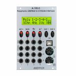
People also bought...
Doepfer A-190-5 Polyphonic USB/MIDI To CV/Gate Interface Module (silver) (MIDI/quad synth module)
Cat: 676695 Rel: 20 Dec 18 • View all Synth modules
Four-channel MIDI-CV interface for playing polyphonic patches - 16HP
Notes: Module A-190-5 is a four voice Midi/USB to CV/Gate interface. For each voice a pitch control voltage (CV1, 1V/octave standard to control VCOs), a gate output (to control envelope generators) and two additional control voltages (CV2, CV3) are available. The two additional CV outputs can be controlled by Midi velocity, volume, modulation, pitch bend, after touch or free assignable Midi controllers.
- Four voice monophonic (i.e. to control four monophonic voices by four succeeding Midi channels)
- Four voice polyphonic (i.e. to control four monophonic voices by one Midi channel) with several sub-modes (e.g. rotating/non-rotating)
- Two voice polyphonic (i.e. to control two monophonic voices by one Midi channel)
- Unisono
The basic mode is selected by means of a momentary switch (probably Mode or Algor.) and is shown in the LC display. Certain parameters of each mode can be edited (e.g. the midi channel(s), the midi reference note for 0V CV, assigned controllers for CV2 and CV3). For this the momentary switch Edit/Play is used. The parameter values (e.g. midi channels) are shown in the display and can be modified by means of the momentary switches 1...4. In Play mode the LEDs of these four switches display the gate states.
… Read more- Four voice monophonic (i.e. to control four monophonic voices by four succeeding Midi channels)
- Four voice polyphonic (i.e. to control four monophonic voices by one Midi channel) with several sub-modes (e.g. rotating/non-rotating)
- Two voice polyphonic (i.e. to control two monophonic voices by one Midi channel)
- Unisono
The basic mode is selected by means of a momentary switch (probably Mode or Algor.) and is shown in the LC display. Certain parameters of each mode can be edited (e.g. the midi channel(s), the midi reference note for 0V CV, assigned controllers for CV2 and CV3). For this the momentary switch Edit/Play is used. The parameter values (e.g. midi channels) are shown in the display and can be modified by means of the momentary switches 1...4. In Play mode the LEDs of these four switches display the gate states.
out of stock $287.50
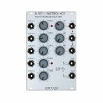
People also bought...
Doepfer A-101-1 Vactrol VCF Vactrol Multi-Type Input Filter Module (silver) (filter synth module)
Cat: 682307 Rel: 06 Apr 18 • View all Synth modules
Vactrol-based multimode filter based on a schematic by Nyle Steiner, featuring separate inputs for lowpass, bandpass & highpass
Notes: This filter's unique feature is that different filter types are realized by injecting the audio signal at different points of the circuit. For this reason, the A-101-1 has three inputs with level control: one lowpass input which is normalized to the bandpass input, which itself is normalized to the highpass input. The level controls make it possible to mix the filters and to generate new filter types. e.g. with all three filter levels turned to maximum level you get a notch filter.
Furthermore, the cutoff frequency influences which filter type is "monitored". This way you can blend from LP over BP to HP with increasing cutoff, known as "frequency scanning". Interesting effects happen when three different audio signals are used because they are both morphed and filtered at the same time.
… Read moreFurthermore, the cutoff frequency influences which filter type is "monitored". This way you can blend from LP over BP to HP with increasing cutoff, known as "frequency scanning". Interesting effects happen when three different audio signals are used because they are both morphed and filtered at the same time.
out of stock $122.47
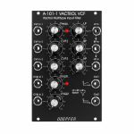
People also bought...
Doepfer A-101-1v Vactrol Multi-Type Input Filter Vintage Edition Module (black) (filter synth module)
Cat: 682313 Rel: 26 Mar 18 • View all Synth modules
Vactrol-based multimode filter based on a schematic by Nyle Steiner, featuring separate inputs for lowpass, bandpass & highpass
Notes: This filter's unique feature is that different filter types are realized by injecting the audio signal at different points of the circuit. For this reason, the A-101-1 has three inputs with level control: one lowpass input which is normalized to the bandpass input, which itself is normalized to the highpass input. The level controls make it possible to mix the filters and to generate new filter types. e.g. with all three filter levels turned to maximum level you get a notch filter.
Furthermore, the cutoff frequency influences which filter type is "monitored". This way you can blend from LP over BP to HP with increasing cutoff, known as "frequency scanning". Interesting effects happen when three different audio signals are used because they are both morphed and filtered at the same time.
Vintage edition with black faceplate and custom knobs.
… Read moreFurthermore, the cutoff frequency influences which filter type is "monitored". This way you can blend from LP over BP to HP with increasing cutoff, known as "frequency scanning". Interesting effects happen when three different audio signals are used because they are both morphed and filtered at the same time.
Vintage edition with black faceplate and custom knobs.
out of stock $138.04
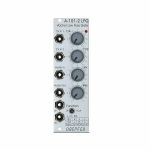
People also bought...
Doepfer A-101-2 LPG Vactrol Low Pass Gate Module (silver) (low pass gate/filter/VCA synth module)
Cat: 682314 Rel: 26 Mar 18 • View all Synth modules
Vactrol based combination of resonant 12dB lowpass filter and/or VCA - inspired by the Buchla 292
Notes: A Low Pass Gate (LPG) can be a low pass filter, a VCA or a combination of both. This means both the harmonic content and volume can be controlled simultaneously which resembles the behaviour of many instruments: the louder, the more harmonics.
The A-101-2's mode of operation is set with a switch: left position is low pass, right is VCA and the combo mode is in the centre. Alternatively, you can activate the modes with gate signals which is the reason for two gate inputs; this is very interesting in combination with clock dividers or trigger sequencers.
- Gate 1 high & gate 2 low = low pass mode
- Gate 1 low & gate 2 high = VCA mode
- Both Gate 1 & 2 high = combo mode
The A-101-2 has an aggressive sound, compared to other LPGs and its resonance goes up to self-oscillation which not many LPGs offer. The oscillation is rather dirty and far from being a sine wave.
3U Eurorack module, 8HP wide, 50mm deep.
… Read moreThe A-101-2's mode of operation is set with a switch: left position is low pass, right is VCA and the combo mode is in the centre. Alternatively, you can activate the modes with gate signals which is the reason for two gate inputs; this is very interesting in combination with clock dividers or trigger sequencers.
- Gate 1 high & gate 2 low = low pass mode
- Gate 1 low & gate 2 high = VCA mode
- Both Gate 1 & 2 high = combo mode
The A-101-2 has an aggressive sound, compared to other LPGs and its resonance goes up to self-oscillation which not many LPGs offer. The oscillation is rather dirty and far from being a sine wave.
3U Eurorack module, 8HP wide, 50mm deep.
out of stock $97.56

People also bought...
Cat: 682317 Rel: 26 Mar 18 • View all Synth modules
Vactrol based combination of resonant 12dB lowpass filter and/or VCA - inspired by the Buchla 292
Notes: A Low Pass Gate (LPG) can be a low pass filter, a VCA or a combination of both. This means both the harmonic content and volume can be controlled simultaneously which resembles the behaviour of many instruments: the louder, the more harmonics.
The A-101-2's mode of operation is set with a switch: left position is low pass, right is VCA and the combo mode is in the centre. Alternatively, you can activate the modes with gate signals which is the reason for two gate inputs; this is very interesting in combination with clock dividers or trigger sequencers.
- Gate 1 high & gate 2 low = low pass mode
- Gate 1 low & gate 2 high = VCA mode
- Both Gate 1 & 2 high = combo mode
The A-101-2 has an aggressive sound, compared to other LPGs and its resonance goes up to self-oscillation which not many LPGs offer. The oscillation is rather dirty and far from being a sine wave.
Vintage edition with black faceplate and custom knobs.
3U Eurorack module, 8HP wide, 50mm deep.
… Read moreThe A-101-2's mode of operation is set with a switch: left position is low pass, right is VCA and the combo mode is in the centre. Alternatively, you can activate the modes with gate signals which is the reason for two gate inputs; this is very interesting in combination with clock dividers or trigger sequencers.
- Gate 1 high & gate 2 low = low pass mode
- Gate 1 low & gate 2 high = VCA mode
- Both Gate 1 & 2 high = combo mode
The A-101-2 has an aggressive sound, compared to other LPGs and its resonance goes up to self-oscillation which not many LPGs offer. The oscillation is rather dirty and far from being a sine wave.
Vintage edition with black faceplate and custom knobs.
3U Eurorack module, 8HP wide, 50mm deep.
out of stock $97.56

People also bought...
Doepfer A-123-2 6/12/18/24dB Highpass Filter Module (synth module)
Cat: 684442 Rel: 30 Oct 18 • View all Synth modules
Voltage controlled highpass filter - 8HP
Notes: A-123-2 is a voltage controlled high-pass filter with four filter outputs (6, 12, 18 and 24dB slope). It also features voltage control of the resonance.
These controls and in/outputs are available:
- Audio In with attenuator (Lev)
- Manual Frequency control (Frq)
- FCV1: Frequency control input (~ 1V/oct)
- FCV2: Frequency control input with polarizer
- QCV: Resonance control input with attenuator
- Manual Resonance control (Q)
- 6dB Output
- 12dB Output
- 18dB Output
- 24dB Output
… Read moreThese controls and in/outputs are available:
- Audio In with attenuator (Lev)
- Manual Frequency control (Frq)
- FCV1: Frequency control input (~ 1V/oct)
- FCV2: Frequency control input with polarizer
- QCV: Resonance control input with attenuator
- Manual Resonance control (Q)
- 6dB Output
- 12dB Output
- 18dB Output
- 24dB Output
out of stock $103.79

People also bought...
Doepfer A-150v Dual Voltage Controlled Switch Vintage Edition Module (black) (dual/stereo/switch synth module)
Cat: 684460 Rel: 23 Apr 18 • View all Synth modules
Two independent voltage controlled switches in one module - 4HP
Notes: Module A-150 (Dual VCS) contains two separate voltage-controlled switches.
Each switch has a control voltage input, a common Out / Input, and two In / Outputs. The switches are bi-directional: they can work in both directions, so can connect one input to either of two outputs, or either of two inputs to one output. Voltages in the range -8V...+8V at the O/I resp. I/O sockets can be processed by the module.
Two LEDs show which in / output is active (i.e. which is connected to the common out / input).
… Read moreEach switch has a control voltage input, a common Out / Input, and two In / Outputs. The switches are bi-directional: they can work in both directions, so can connect one input to either of two outputs, or either of two inputs to one output. Voltages in the range -8V...+8V at the O/I resp. I/O sockets can be processed by the module.
Two LEDs show which in / output is active (i.e. which is connected to the common out / input).
out of stock $62.26

People also bought...
Doepfer A-102 VCF9 Diode Low Pass Filter Module (silver) (filter synth module)
Cat: 692503 Rel: 18 Jun 18 • View all Synth modules
Reproduction of the legendary British diode lowpass filter - 8HP
Notes: Module A-102 is a reproduction of the legendary low pass filter design that uses diodes in the filter stage as frequency controlling elements - resulting in "strange" resonance behaviour and frequency response, as resonance and frequency are not independent from another.
As for the rest, the A-102 is identical to the A-120 Moog low pass filter, the A-103 (18dB TB303 Filter) i.e. the same controls, inputs and outputs. Only the filter sound is different:
- Manual control of filter frequency
- 3 CV inputs (CV1, CV2, CV3), 2 of them with attenuator (CV2, CV3)
- Input level control
- Resonance control up to self-oscillation (depends upon the frequency setting for the A-102)
… Read moreAs for the rest, the A-102 is identical to the A-120 Moog low pass filter, the A-103 (18dB TB303 Filter) i.e. the same controls, inputs and outputs. Only the filter sound is different:
- Manual control of filter frequency
- 3 CV inputs (CV1, CV2, CV3), 2 of them with attenuator (CV2, CV3)
- Input level control
- Resonance control up to self-oscillation (depends upon the frequency setting for the A-102)
out of stock $81.99
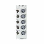
People also bought...
Doepfer A-103 VCF6 18dB Low Pass Filter Module (filter synth module)
Cat: 692504 Rel: 18 Jun 18 • View all Synth modules
18dB low pass filter based on a modified Moog cascade - 8HP
Notes: Module A-103 is a voltage controlled low pass filter with 18dB/octave slope. The circuit is based on a modified transistor ladder (Moog ladder) and is a reproduction of the legendary TB303 filter.
As for the rest the A-103 is identical to the A-120 Moog low pass filter (same controls, inputs/outputs) only the filter sound is different.
… Read moreAs for the rest the A-103 is identical to the A-120 Moog low pass filter (same controls, inputs/outputs) only the filter sound is different.
1 in stock $89.25
Click for better price!
or call +44 20 7424 1960
quote 692504
quote 692504

People also bought...
Doepfer A-104 Trautonium Formant Filter Module (filter/equalizer module)
Cat: 692505 Rel: 18 Jun 18 • View all Synth modules
Quad resonance filter module - 20HP
Notes: A-104 is a fourfold formant filter as used in the Mixtur Trautonium by Oskar Sala. It is made of four parallel resonance filters, each filter can be switched to low pass or band pass or off. Frequency, resonance and level are controlled for each filter separately (no voltage control). The frequency range for the filters is about 50Hz...5kHz. The filter audio inputs are very sensitive so that distortion may intentionally be used to create new sounds - if desired. The sketch below shows the basic layout of the A-104. The A-104 is a versatile module for sound modification. In the first place it is used for reproduction of resonances (e.g. the vocal-like effects known from the Trautonium). In combination with the subharmonic generator A-113, the Trautonium Manual A-198 and some other A-100 modules one obtains a Trautonium replica. More detailed information about the Trautonium can be found on our internet site.
Dimensions
20 HP
45 mm deep
Current Draw
30 mA +12V
10 mA -12V
… Read moreDimensions
20 HP
45 mm deep
Current Draw
30 mA +12V
10 mA -12V
out of stock $124.54

People also bought...
Doepfer A-106-1 Xtreme Filter Voltage Controlled Lowpass & Highpass Filter Module (silver) (filter synth module)
Cat: 692507 Rel: 19 Jun 18 • View all Synth modules
MS20 low/high-pass filter - 14HP
Notes: Module A-106-1 is a unique low/high pass filter and has its origin in Doepfer's experiments to build an MS20 filter clone. In contrast to other filter designs, it has different audio inputs for low and high pass, but only one audio output. The type of filter (12dB low pass, 6dB high pass or any mix) is defined by the shares of the audio signal fed to the corresponding inputs. Even two different audio signals can be used as low and high pass input. A special feature is the polarizer at the high pass input that allows to add/subtract the high pass to/from the low pass share, leading to pseudo band pass and notch responses.
Another special feature is the clipping controls, which allow independent adjustment of the positive and negative clipping level. The resonance goes up to self-oscillation, but with a clearly different behaviour than on other filters. At certain resonance and clipping settings the self-oscillation generates rectangle or short sawtooth shaped pulses.
In general, the A-106-1 is a very strange and awesome filter and far away from being perfect (e.g non-linear control scale, self-oscillation with all sorts of waveforms except sine, a lot of roaring, rattling, noise or other unpredictable sounds at high distortion and resonance settings, high distortion or audio level overrides the resonance, significant CV feedthrough). But the A-106-1 has a lot of character - probably much more than any other filter of the A-100 - and is able to generate filter sweeps which are not possible with any other filter.
… Read moreAnother special feature is the clipping controls, which allow independent adjustment of the positive and negative clipping level. The resonance goes up to self-oscillation, but with a clearly different behaviour than on other filters. At certain resonance and clipping settings the self-oscillation generates rectangle or short sawtooth shaped pulses.
In general, the A-106-1 is a very strange and awesome filter and far away from being perfect (e.g non-linear control scale, self-oscillation with all sorts of waveforms except sine, a lot of roaring, rattling, noise or other unpredictable sounds at high distortion and resonance settings, high distortion or audio level overrides the resonance, significant CV feedthrough). But the A-106-1 has a lot of character - probably much more than any other filter of the A-100 - and is able to generate filter sweeps which are not possible with any other filter.
out of stock $108.98

People also bought...
Doepfer A-106-6 XP VCF 16-Fold VC Xpander Filter Module (silver) (filter/oscillator module)
Cat: 692508 Rel: 19 Jun 18 • View all Synth modules
Multimode filter based on the filter circuit of the Oberheim Xpander - 12HP
Notes: Module A-106-6 is a multimode filter that is based on the filter circuit of the Oberheim Xpander. The module features 15 different filter types (those filters of the A-107 that were available in the Xpander) with 8 filters available simultaneously. The toggle switch Filter Group is used to switch between 2 filter groups.
These filter types are available:
- 1L (6 dB low pass)
- 2L (12 dB low pass)
- 3L (18 dB low pass)
- 4L (24 dB low pass)
- 1H (6 dB high pass)
- 2H (12 dB high pass)
- 3H (18 dB high pass)
- 2B (6 dB band pass)
- 4B (12 dB bandpass)
- 2N (notch)
- 3A (allpass)
- 2H1L (asymmetrical band pass made of a 12 dB high pass and a 6 dB low pass)
- 3H1L (asymmetrical band pass made of a 18 dB high pass and a 6 dB low pass)
- 2N1L (combination of notch and 6 dB low pass)
- 3A1L (combination of allpass and 6 dB low pass)
The module features voltage-controlled resonance. For filter group 2 (2L, 4L, 2B ...) even self-oscillation is possible.
All standard VCF controls are available: manual filter frequency control Frq, one control voltage input with attenuator (FCV2) and one without attenuator (FCV1, ~ 1 V/octave). In addition, voltage-controlled resonance with manual control (Q) and a CV input with attenuator (QCV) are available.
The circuit is based on a 24dB lowpass filter. The outputs of the four internal filter stages (i.e. the 6, 12, 18 and 24dB outputs) are mixed together with different levels and polarities to obtain 15 different filters. Because of this special circuit the outputs have slightly different levels and noise floor. This is caused by the different internal amplifications and numbers of stages that are required to generate the filter in question. If e.g. a filter is derived by one stage only (e.g. the 6 dB, 12dB, 18dB and 24dB low pass) the noise floor is smaller compared to a filter that is derived by a combination of all four filter stages.
… Read moreThese filter types are available:
- 1L (6 dB low pass)
- 2L (12 dB low pass)
- 3L (18 dB low pass)
- 4L (24 dB low pass)
- 1H (6 dB high pass)
- 2H (12 dB high pass)
- 3H (18 dB high pass)
- 2B (6 dB band pass)
- 4B (12 dB bandpass)
- 2N (notch)
- 3A (allpass)
- 2H1L (asymmetrical band pass made of a 12 dB high pass and a 6 dB low pass)
- 3H1L (asymmetrical band pass made of a 18 dB high pass and a 6 dB low pass)
- 2N1L (combination of notch and 6 dB low pass)
- 3A1L (combination of allpass and 6 dB low pass)
The module features voltage-controlled resonance. For filter group 2 (2L, 4L, 2B ...) even self-oscillation is possible.
All standard VCF controls are available: manual filter frequency control Frq, one control voltage input with attenuator (FCV2) and one without attenuator (FCV1, ~ 1 V/octave). In addition, voltage-controlled resonance with manual control (Q) and a CV input with attenuator (QCV) are available.
The circuit is based on a 24dB lowpass filter. The outputs of the four internal filter stages (i.e. the 6, 12, 18 and 24dB outputs) are mixed together with different levels and polarities to obtain 15 different filters. Because of this special circuit the outputs have slightly different levels and noise floor. This is caused by the different internal amplifications and numbers of stages that are required to generate the filter in question. If e.g. a filter is derived by one stage only (e.g. the 6 dB, 12dB, 18dB and 24dB low pass) the noise floor is smaller compared to a filter that is derived by a combination of all four filter stages.
out of stock $144.27

People also bought...
Doepfer A-107 Multitype Morphing Filter Module (synth module)
Cat: 692509 Rel: 18 Jun 18 • View all Synth modules
Voltage controlled filter with 36 filter types - 26HP
Notes: This module contains 26 very different filter types which can be combined each after the other. You can morph or switch between those filter chains manually, with control voltage or with a clock signal. 15 filter types are known from the Oberheim Matrix 12 and there additional 21 new filter types.
The filters are organized in two groups of 18 filters each. The transition between different filter types within one group can be soft (morphing) or hard (switching).
The transition between the different filter types is controlled by two parameters: Filter Step (marked Step at the front panel) and Morphing Time (marked Morph at the front panel). For both parameters manual control, one CV input with attenuator and one CV input without attenuator are available.
The 36 filter types can be arranged in filter chains (resp. filter sequencer or filter orders) so that this sequence of filters is passed through while the control voltage changes from 0V to +5V. Each chain consists of 32 steps. 64 filter chains can be programmed by the user and stored in the non-volatile memory of the module.
Of course, the standard VCF controls are available: cut-off frequency and resonance. Both are voltage controllable. For the filters of the first group (1-18) self-oscillation is possible, the filters of the second group (19-36) do not feature self-oscillation.
The filter design is 100% analogue (CEM filter chip). Only the morphing control and memory managing is carried out by a microcontroller.
… Read moreThe filters are organized in two groups of 18 filters each. The transition between different filter types within one group can be soft (morphing) or hard (switching).
The transition between the different filter types is controlled by two parameters: Filter Step (marked Step at the front panel) and Morphing Time (marked Morph at the front panel). For both parameters manual control, one CV input with attenuator and one CV input without attenuator are available.
The 36 filter types can be arranged in filter chains (resp. filter sequencer or filter orders) so that this sequence of filters is passed through while the control voltage changes from 0V to +5V. Each chain consists of 32 steps. 64 filter chains can be programmed by the user and stored in the non-volatile memory of the module.
Of course, the standard VCF controls are available: cut-off frequency and resonance. Both are voltage controllable. For the filters of the first group (1-18) self-oscillation is possible, the filters of the second group (19-36) do not feature self-oscillation.
The filter design is 100% analogue (CEM filter chip). Only the morphing control and memory managing is carried out by a microcontroller.
out of stock $265.70

People also bought...
Doepfer A-108 6/12/24/48dB Low Pass Filter Module (filter synth module)
Cat: 692510 Rel: 19 Jun 18 • View all Synth modules
Classic Moog voltage-controlled lowpass filter - 12HP
Notes: Module A-108 is a completely new voltage-controlled low pass filter based on the well-known transistor ladder (Moog ladder). The module has internally an 8-stage low pass filter with different slopes available: 6, 12, 18, 24, 30, 36, 42 and 48 dB per octave. In addition, it features a band pass output (i.e. band pass with transistor ladder). In the factory, the 4 low pass outputs of the A-108 are internally connected to the filter stages 6, 12, 24 and 48dB.
Resonance (Emphasis or Q) can be adjusted manually right up to self-oscillation, in which case the filter will behave like a sine wave oscillator. The A-108 features an external feedback input that enables the insertion of additional modules into the feedback path (e.g. VCA for voltage-controlled resonance or phaser/frequency shifter for phase/frequency shifting effects). The socket is normalized and internally connected to the 48dB low pass output if no cable is inserted into the feedback socket.
The frequency can be adjusted manually, or by voltage control. Three CV inputs (CV1, CV2, CV3) are available. CV2 and CV3 are equipped with attenuators.
The filter audio input is very sensitive so that distortion - if desired - is possible even with normal A-100 levels (e.g. VCO output). Self-oscillation will break off at high distortion levels as the internal feedback signal is drown out by the distorted audio signal. This feature may intentionally be used to create new sounds.
In combination with the Voltage Controlled Mixer A-135 and the Morphing Controller A-144 a filter with voltage-controlled slope can be realized (i.e. controlling the slope from 6dB to 48dB via CV).
… Read moreResonance (Emphasis or Q) can be adjusted manually right up to self-oscillation, in which case the filter will behave like a sine wave oscillator. The A-108 features an external feedback input that enables the insertion of additional modules into the feedback path (e.g. VCA for voltage-controlled resonance or phaser/frequency shifter for phase/frequency shifting effects). The socket is normalized and internally connected to the 48dB low pass output if no cable is inserted into the feedback socket.
The frequency can be adjusted manually, or by voltage control. Three CV inputs (CV1, CV2, CV3) are available. CV2 and CV3 are equipped with attenuators.
The filter audio input is very sensitive so that distortion - if desired - is possible even with normal A-100 levels (e.g. VCO output). Self-oscillation will break off at high distortion levels as the internal feedback signal is drown out by the distorted audio signal. This feature may intentionally be used to create new sounds.
In combination with the Voltage Controlled Mixer A-135 and the Morphing Controller A-144 a filter with voltage-controlled slope can be realized (i.e. controlling the slope from 6dB to 48dB via CV).
out of stock $136.96

People also bought...
Doepfer A-110-1v Standard VCO Module (vintage edition) (synth module)
Cat: 692511 Rel: 19 Jun 18 • View all Synth modules
Standard VCO providing two CV inputs for pitch, an octave switch, four waveforms with separate outputs, pulse width modulation & hard sync - 10HP
Notes: Module A-110-1 is a voltage-controlled oscillator. This VCO's frequency range is about eight octaves (ca. 15Hz ... 8kHz). It can produce four waveforms simultaneously: rectangle, sawtooth, triangle, and sine wave (triangle and sine shapes are not perfect, see remark below). The output levels are typically 8Vpp for saw and rectangle, and 10Vpp for triangle and sine. The frequency or pitch of the VCO is determined by the position of the octave (Range) switch and tuning (Tune) knob, and by the voltage present at the CV inputs. Frequency modulation (FM) of the VCO is therefore a possibility. Footage (the octave of the fundamental) is set by the Range control in five steps, and Fine tuning controlled by the Tune knob by about +/-1 one semitone (can be modified for a wider range).
You can control the pulse width of the square wave either by hand, or by voltage control - Pulse Width Modulation or PWM.
For more detailed information please look at the user's manual A110_man.pdf. In addition, the A-110 service manual is available as an example for the A-100 service manual that is available at extra charges. This document describes also how to modify the sensitivity of the tune control, how to re-adjust the 1V/octave scale and the frequency offset (i.e. the absolute pitch). Such modifications should be carried out by experienced users only!
The core of the A-110-1 is a sawtooth oscillator (in contrast to the A-111-1, which is based on a triangle oscillator). The other waveforms are derived from the sawtooth by internal waveform converters. As the sawtooth reset (i.e. the back-to-zero slope) is not infinite fast but takes a little bit of time the derived waveforms triangle and sine are not perfect! At the top of the waveform they have a small glitch or notch that is caused by the sawtooth reset and cannot be eliminated by the waveform converters. The sine is derived from the triangle by a simple diode-based converter and the sine shape is not perfect (only a rounded triangle).
If a perfect triangle is required, the A-111-1 is recommended. For a perfect sine wave the quadrature LFO/VCO A-143-9 is recommended.
… Read moreYou can control the pulse width of the square wave either by hand, or by voltage control - Pulse Width Modulation or PWM.
For more detailed information please look at the user's manual A110_man.pdf. In addition, the A-110 service manual is available as an example for the A-100 service manual that is available at extra charges. This document describes also how to modify the sensitivity of the tune control, how to re-adjust the 1V/octave scale and the frequency offset (i.e. the absolute pitch). Such modifications should be carried out by experienced users only!
The core of the A-110-1 is a sawtooth oscillator (in contrast to the A-111-1, which is based on a triangle oscillator). The other waveforms are derived from the sawtooth by internal waveform converters. As the sawtooth reset (i.e. the back-to-zero slope) is not infinite fast but takes a little bit of time the derived waveforms triangle and sine are not perfect! At the top of the waveform they have a small glitch or notch that is caused by the sawtooth reset and cannot be eliminated by the waveform converters. The sine is derived from the triangle by a simple diode-based converter and the sine shape is not perfect (only a rounded triangle).
If a perfect triangle is required, the A-111-1 is recommended. For a perfect sine wave the quadrature LFO/VCO A-143-9 is recommended.
out of stock $144.27

People also bought...
Doepfer A-110-2 Basic VCO Module (synth module)
Cat: 692512 Rel: 18 Jun 18 • View all Synth modules
Basic voltage-controlled oscillator for the A-100 modular system
Notes: Module A-110-2 is a low-cost voltage-controlled oscillator. It's a slightly reduced version of the standard VCO A-110-1. Compared to the A-110-1, the A-110-2 has no sine output and the (expensive) octave rotary switch is replaced by a 3-position toggle switch. In return, the A-110-2 is equipped with an additional linear FM input and a soft sync input. A jumper is used to select the range of the tune control between about 1/2 octave and about 4 octaves. The width of the module is only 8 HP compared to the 10 HP of the A-110-1.
All other features are essentially the same as for the A-110-1.
Explanation of the jumpers and trimming potentiometers:
- JP2: CV connection to A-100 bus
- JP3: range of Tune control (installed = about 4 octaves, not installed = about 1/2 octave)
- JP4: AC/DC coupling of the linear FM input (installed = DC coupling, not installed = AC coupling)
- P5: 1V/Oct scale
- P6: frequency offset
- P7: high-end trim
- P8: adjustment +1 Oct. range switch
- P9: adjustment -1 Oct. range switch
- P10: temperature VCO heater
The core of the A-110-2 is - like the A-110-1 - a sawtooth oscillator (in contrast to the A-111-1, which is based on a triangle oscillator). The other waveforms are derived from the sawtooth by waveform converters. As the sawtooth reset (i.e. the back-to-zero slope) is not infinitely fast but takes a little bit of time the triangle is not perfect! At the bottom of the waveform it has a small glitch or notch that is caused by the sawtooth reset and cannot be eliminated by the waveform converter. If a perfect triangle is required, the A-111-1 is recommended.
The sawtooth output of the A-110-21 has a falling (or negative) slope. The front panel shows erroneously a rising (or positive) slope. This has no influence on the sound but becomes important when the module is used as an LFO or is mixed with the sawtooth output of another VCO.
The control voltage applied to the socket 1V/Oct is added to the control voltage coming from the bus (interruptible by removing the jumper JP2). Connecting a cable to the socket 1V/Oct does not interrupt the bus CV connection!
… Read moreAll other features are essentially the same as for the A-110-1.
Explanation of the jumpers and trimming potentiometers:
- JP2: CV connection to A-100 bus
- JP3: range of Tune control (installed = about 4 octaves, not installed = about 1/2 octave)
- JP4: AC/DC coupling of the linear FM input (installed = DC coupling, not installed = AC coupling)
- P5: 1V/Oct scale
- P6: frequency offset
- P7: high-end trim
- P8: adjustment +1 Oct. range switch
- P9: adjustment -1 Oct. range switch
- P10: temperature VCO heater
The core of the A-110-2 is - like the A-110-1 - a sawtooth oscillator (in contrast to the A-111-1, which is based on a triangle oscillator). The other waveforms are derived from the sawtooth by waveform converters. As the sawtooth reset (i.e. the back-to-zero slope) is not infinitely fast but takes a little bit of time the triangle is not perfect! At the bottom of the waveform it has a small glitch or notch that is caused by the sawtooth reset and cannot be eliminated by the waveform converter. If a perfect triangle is required, the A-111-1 is recommended.
The sawtooth output of the A-110-21 has a falling (or negative) slope. The front panel shows erroneously a rising (or positive) slope. This has no influence on the sound but becomes important when the module is used as an LFO or is mixed with the sawtooth output of another VCO.
The control voltage applied to the socket 1V/Oct is added to the control voltage coming from the bus (interruptible by removing the jumper JP2). Connecting a cable to the socket 1V/Oct does not interrupt the bus CV connection!
out of stock $113.13
